
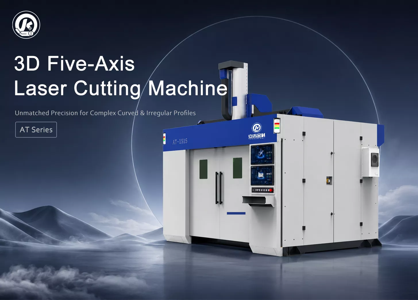
AT Series 3D Five-Axis Laser Cutting Machine
Multi-angle cutting, hole cutting and trimming for formed metal parts.
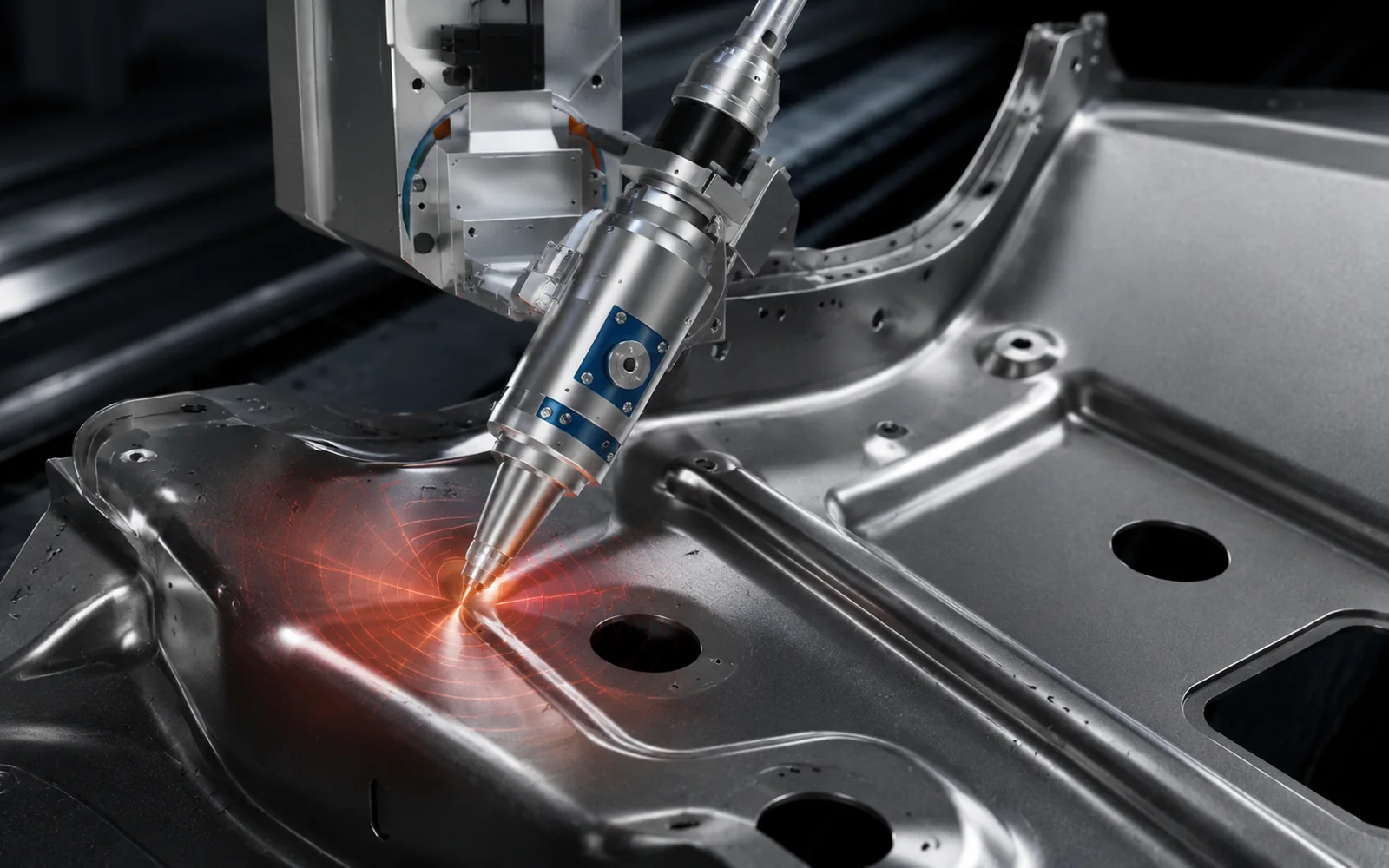
The AT series features a fixed overhead gantry structure, a five-axis simultaneous cutting head, and a 3D programming system, making it ideal for machining tasks that require stable tool paths, flexible production switching, and compatibility with multiple part models.
Send us your 3D model, 2D drawing, material, thickness, production volume and target cycle time. Our technical team will assess tool access, fixturing, cutting paths and machine configuration.
Solve the challenges of complex 3D parts
Complex automotive and other formed components often combine curved surfaces, inclined faces, flanges, deep recesses and holes in several spatial directions. Conventional 2D laser cutting equipment cannot easily reach all these features, while manual trimming depends heavily on operator experience and consistency. For mixed-product manufacturers, the key issues are tool access, repeated clamping, changeover efficiency and batch consistency.
The AT Series combines 3D toolpath planning, teach-in setup and collision detection to help engineers check paths, adjust part orientation and repeat validated programs.
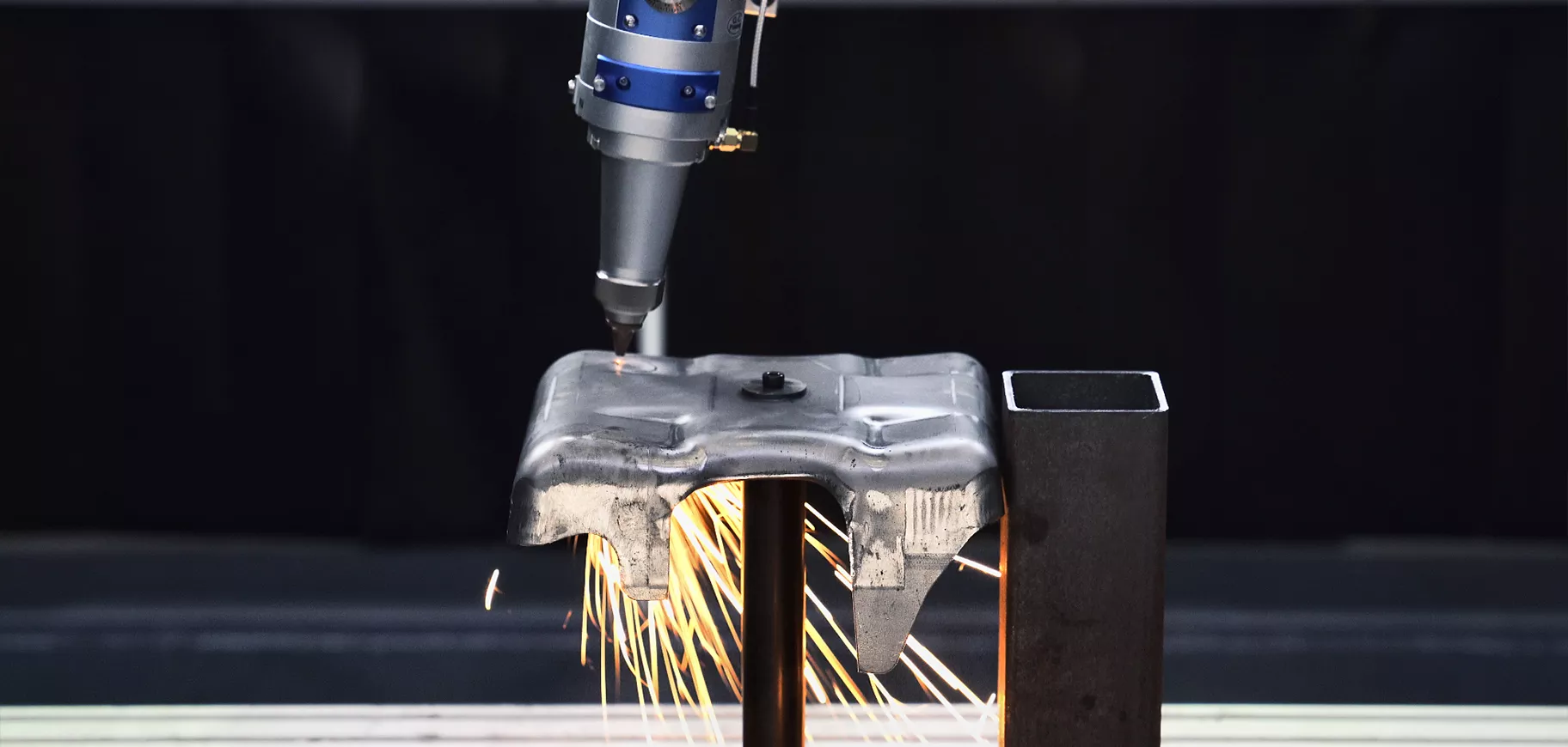
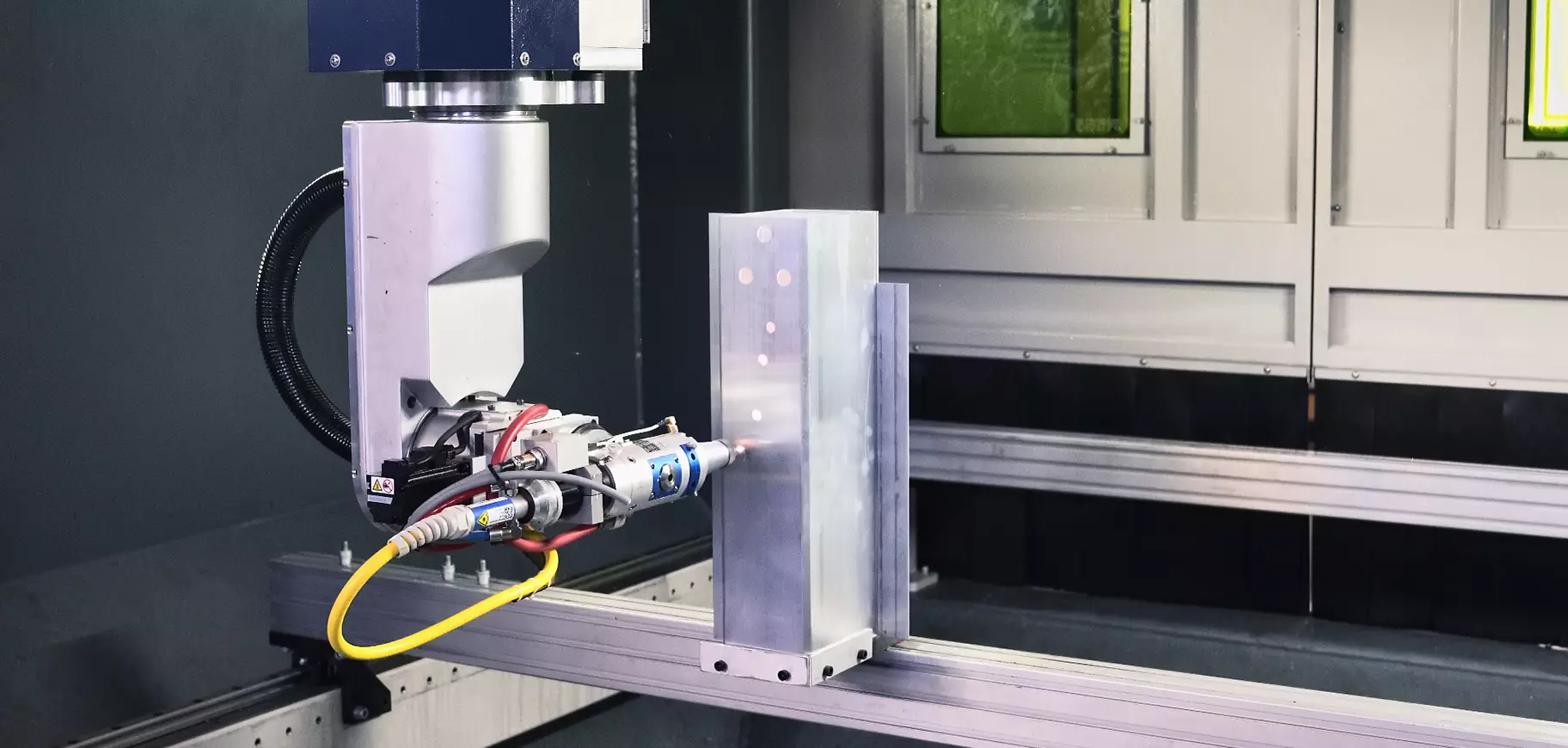
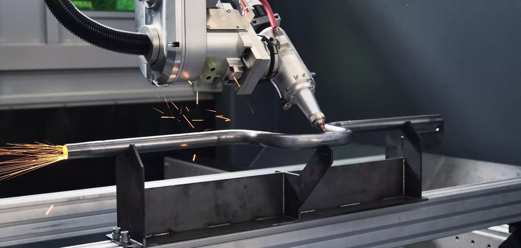
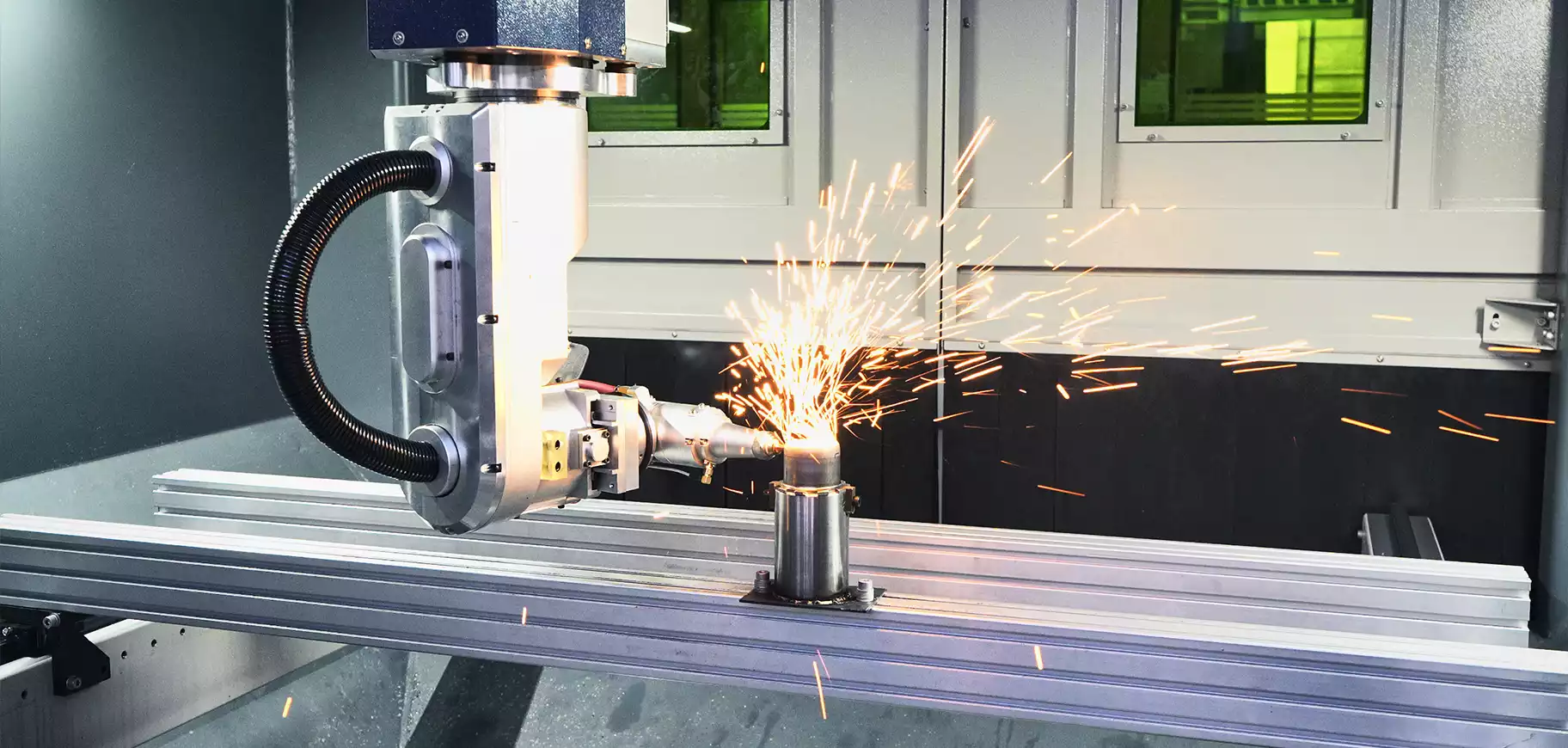
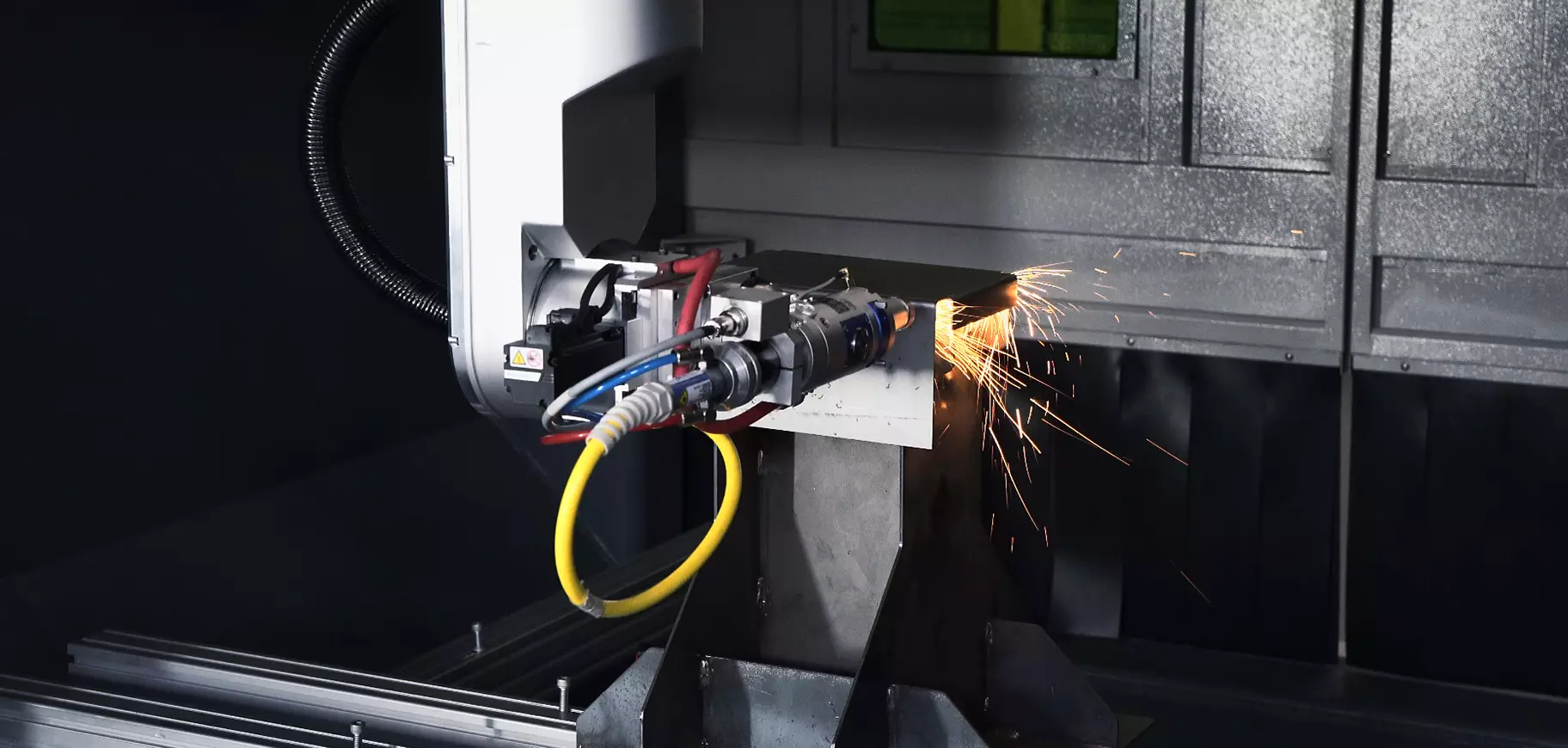
Reach Contours on Different Faces
Cutting features at different angles can fall outside a fixed cutting direction, requiring the part to be turned or another operation to be added.
Reduce Repeated Clamping
Multiple positioning steps increase fixture setup time and cumulative errors, while also extending the cycle time for individual parts.
Respond to Design Changes
Dedicated dies and hard tooling can be costly for prototypes and short runs. Product revisions call for more flexible program and fixture changes.
Verify Complex Toolpaths
Cutting-head orientation, part boundaries and fixture locations need to be checked in advance to reduce interference, collisions and invalid trial cuts.
Multi-angle processing across different industries
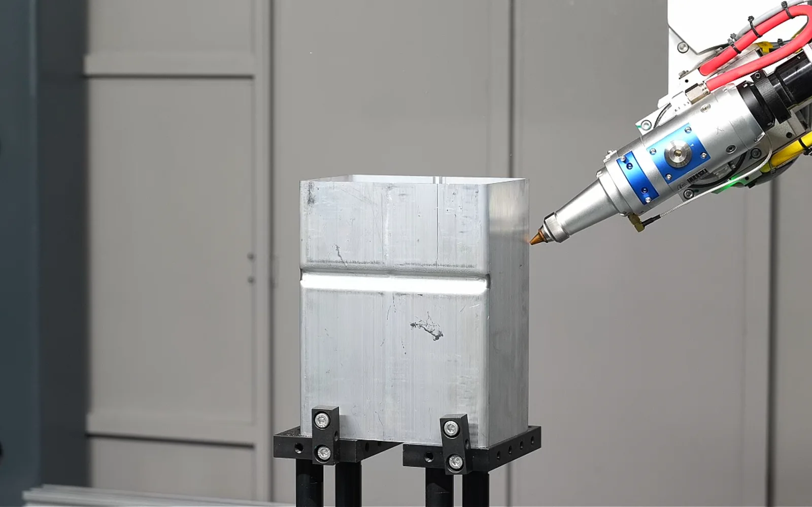
From hot-formed reinforcements and stamped brackets to metal housings and complex frames, start with the features that need cutting to assess whether a five-axis solution fits. Sample displays highlight trimmed edges, spatial holes and multi-angle access so you can compare them with your own parts.
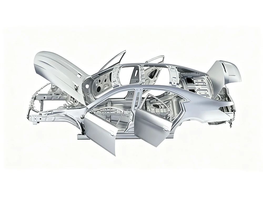
Hot-formed parts, stamped components, body reinforcements and seat structures
Machines multi-angle contours in a single setup; programs adapt to different vehicle models.
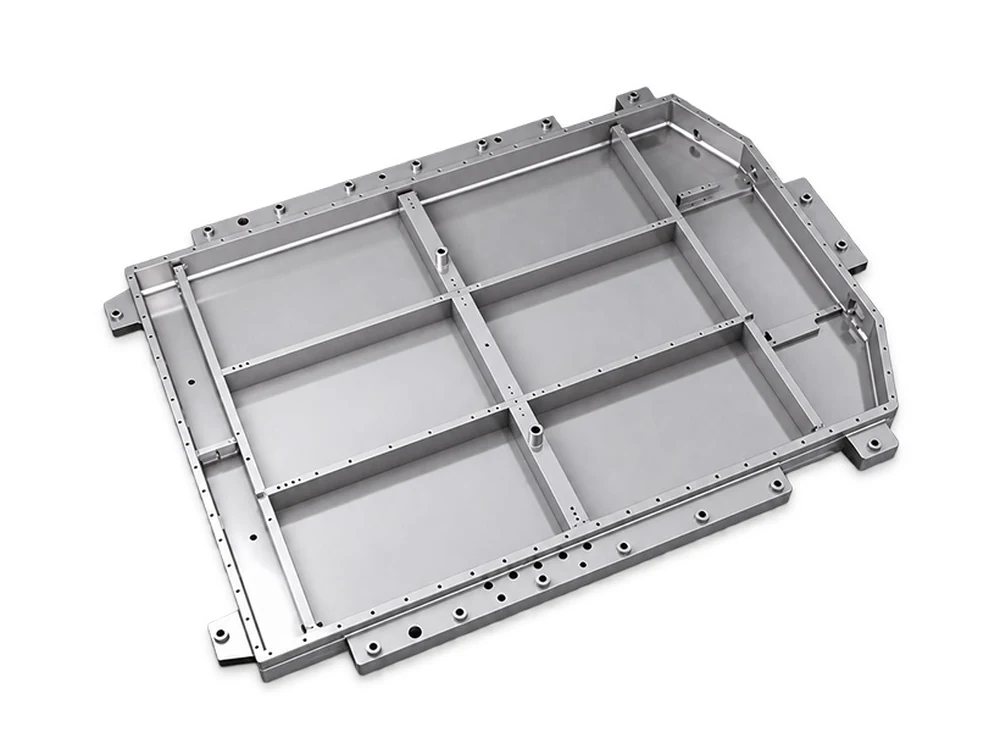
Battery trays, boxes, brackets and housings
A defined working envelope for multi-face cutting and flexible changeovers.
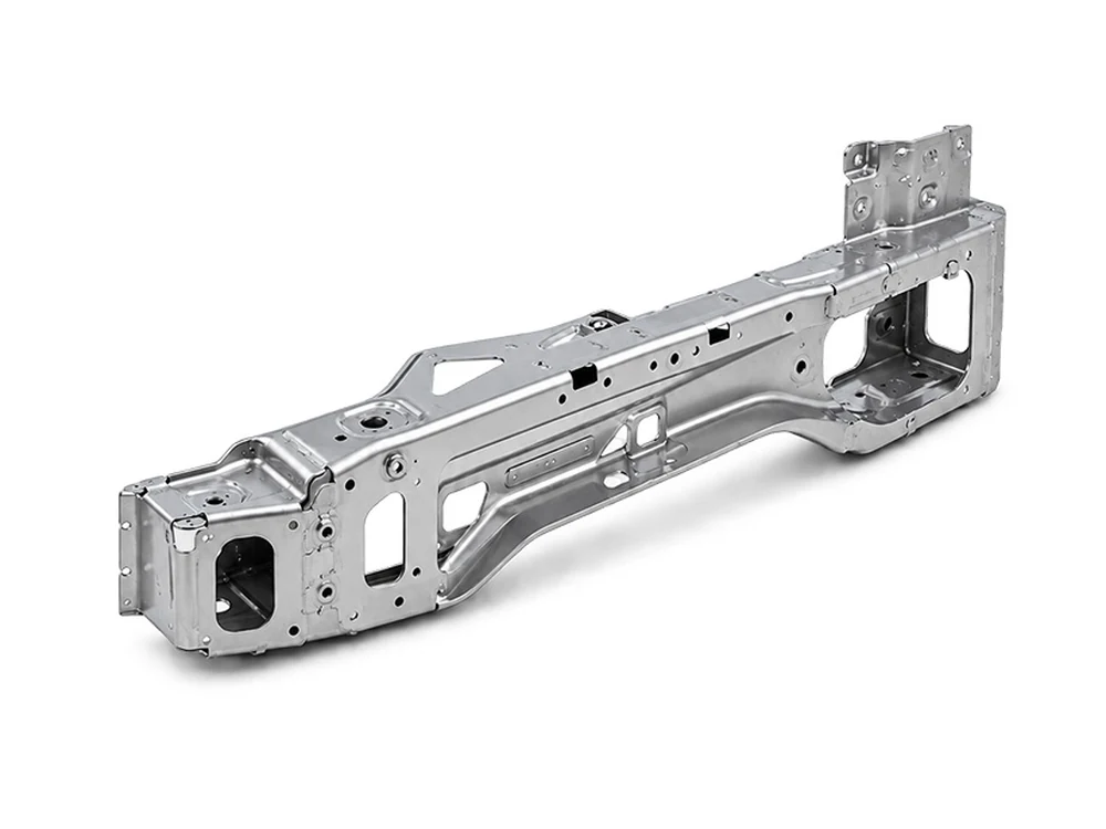
Formed covers, bent structural parts and post-weld components
Improves accessibility via 5-axis orientation, reducing the need for repeated part flipping.
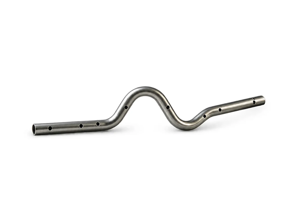
Shaped tubes, profile frames and bent components
Coordinated programs and fixtures for flexible changeovers.
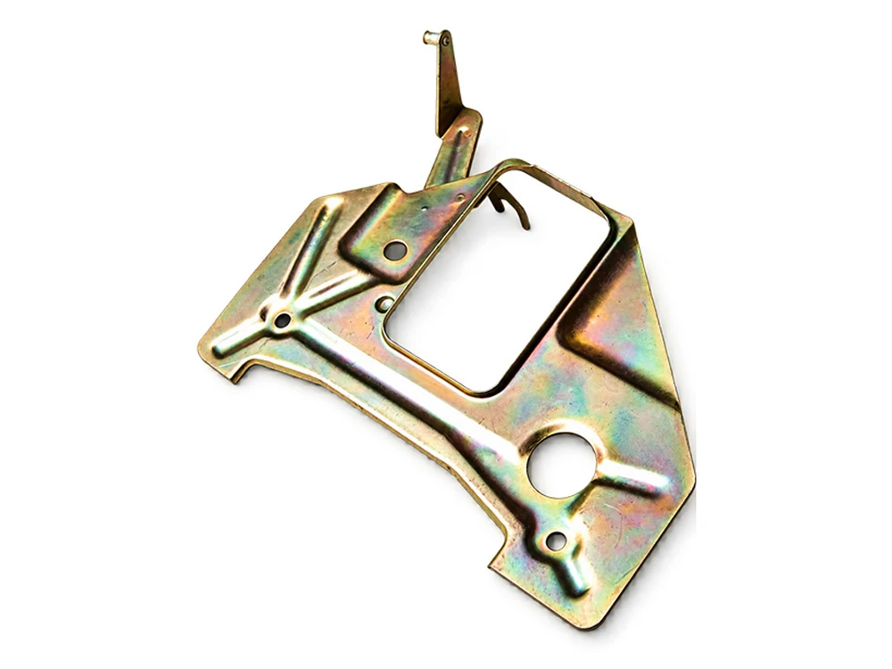
New product samples and short validation runs
Revise 3D paths for prototype development and validation.
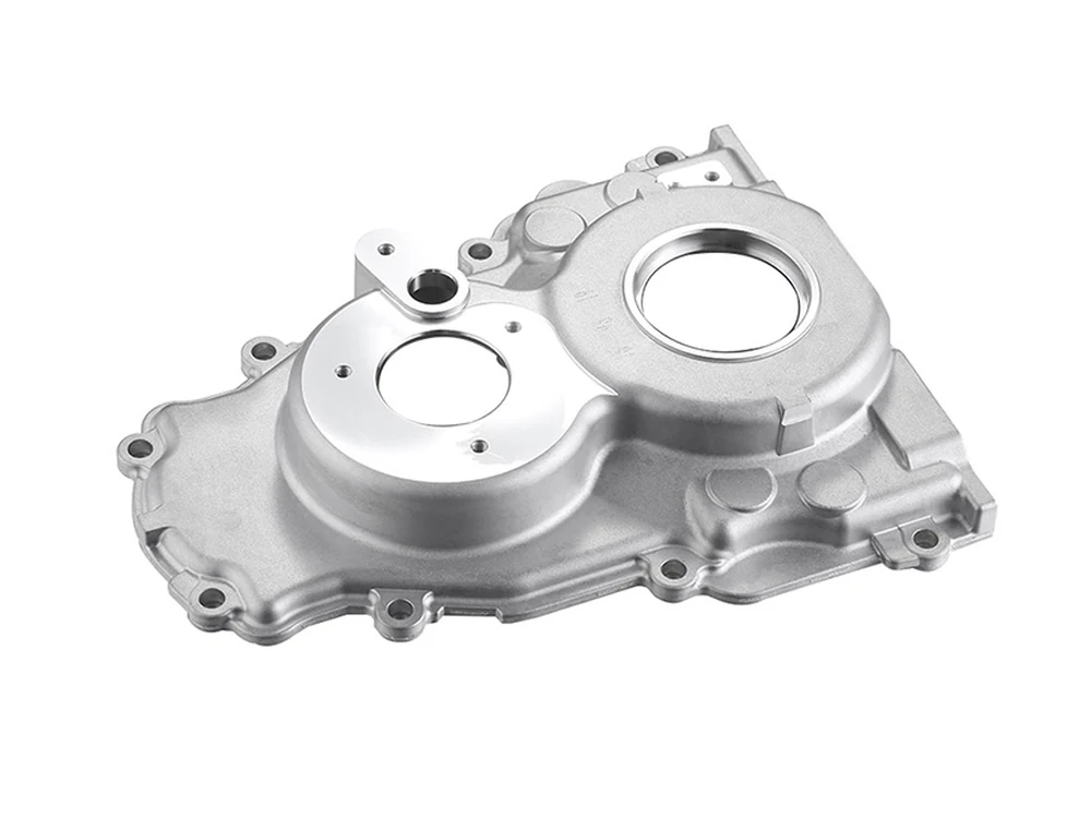
Typical parts and cutting features
Trimmed edges, spatial holes and multi-angle access. Send your part for an application assessment.
Images illustrate application types. They are not customer case-study claims; material, thickness, fixtures and access must be assessed for each part.
A solid mechanical foundation for stable cutting
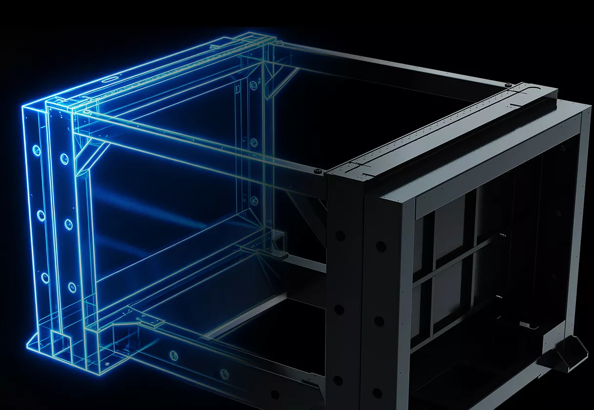
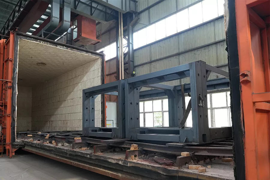
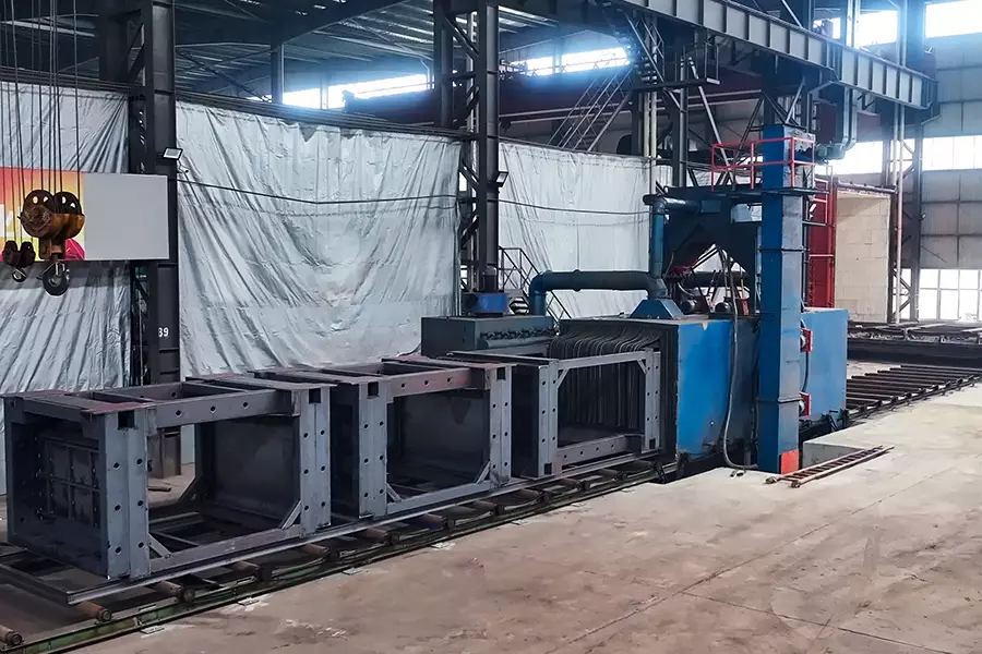
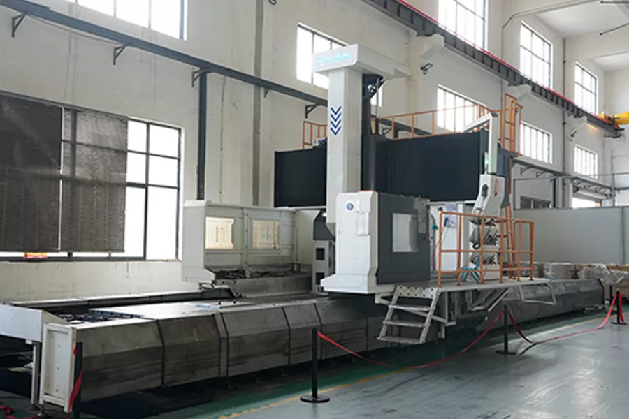
The AT Series uses an integrally welded machine bed and a high-rigidity gantry structure. The bed goes through welding, stress-relief annealing, shot blasting and precision gantry machining before assembly and inspection. Precision-machined mounting surfaces and motion references provide the mechanical foundation for stable multi-axis movement, repeatable paths and long-term operation.
- Integrally welded bed with stress relief and precision machining
- Rigid gantry support for coordinated high-speed motion
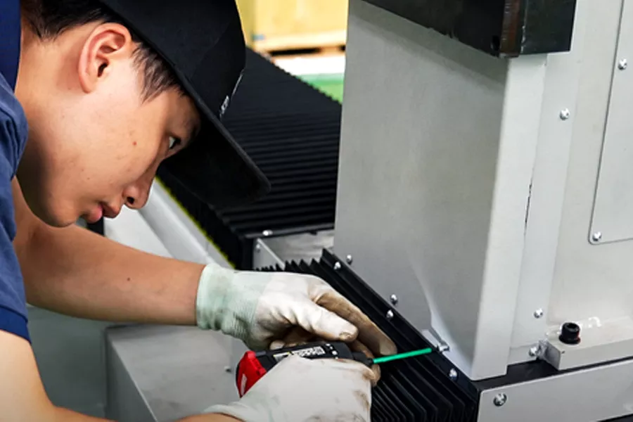
- Key processes completed in-house for control over machining and assembly quality
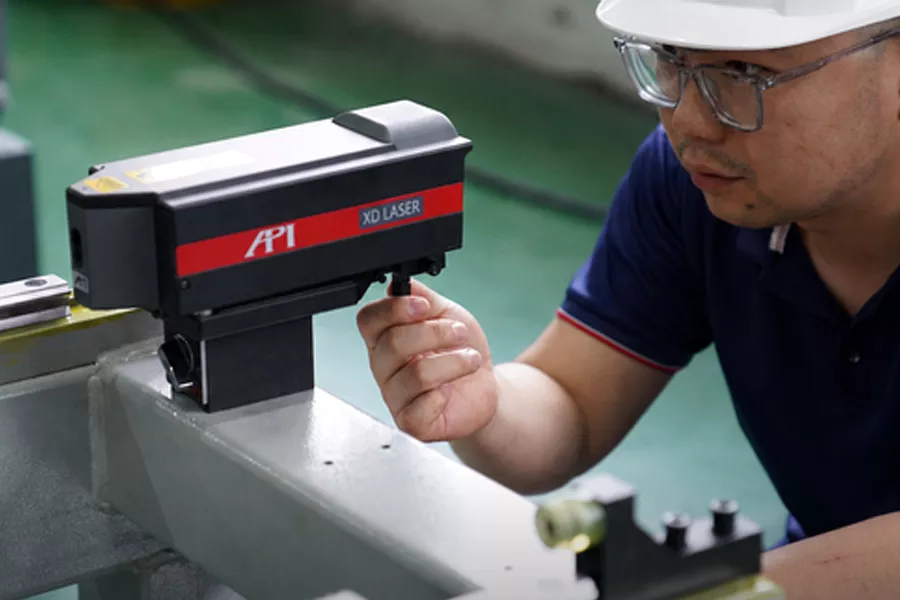
- Verification of motion, functionality, safety, and sample parts performed prior to shipment
Manufacturing and quality control throughout the process
Invest in the details that affect stability and delivery
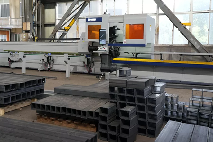
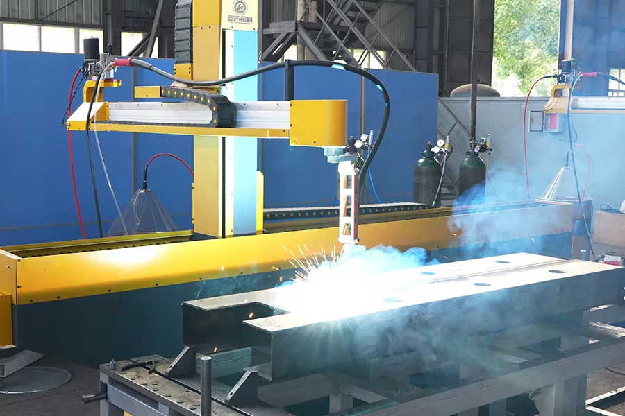
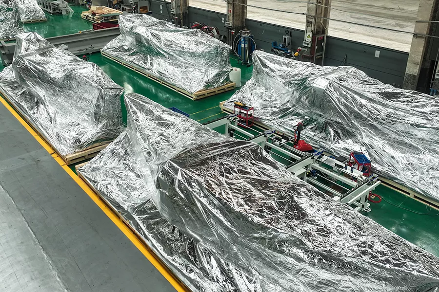
Equipment quality not only comes from the procurement list, but depends on the structural design, machining benchmarks, assembly processes, commissioning methods, and pre-shipment verification. Qingyun integrates key stages—including material preparation, bed welding, stress-relief annealing, shot blasting, precision machining, assembly, inspection and packing for shipment—into a comprehensive manufacturing workflow, facilitating issue traceability and ensuring consistent delivery quality.
Gantry Five-Axis or Robotic Arm Laser Cutting
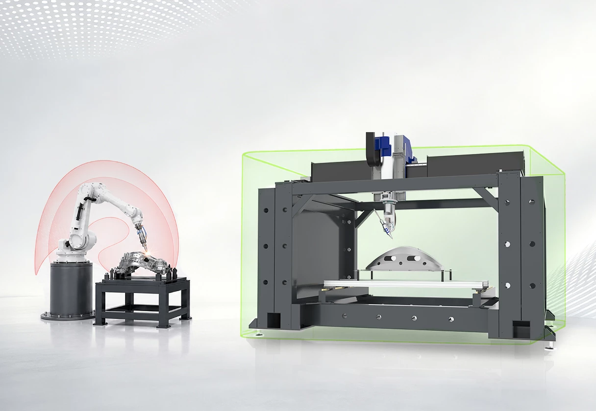
Both robotic arms and fixed-gantry five-axis machines can process three-dimensional parts, but their motion structures, working envelopes and suitable tasks are different.
Robotic arms offer flexible orientations and layout options for tasks that need access from several directions or coordination with other processes.
A fixed-gantry five-axis machine provides linear-axis motion, a rigid structure and a more predictable coverage area within a defined rectangular working envelope.
| Comparison | Fixed-gantry five-axis machine | Robotic-arm solution |
|---|---|---|
| Motion | X, Y and Z linear axes with B and C rotary axes; direct motion relationships | Serial articulated joints; flexible orientation, with paths affected by joint position |
| Rigidity | Fixed bed and gantry suited to stable cutting and trimming | Depends on payload, reach, orientation and end-effector configuration |
| Working area | Defined rectangular envelope for coverage and fixture assessment | Flexible spatial reach; edge regions, singularities and interference require checks |
| Changeovers | Programs and fixtures can serve different parts within the same envelope | Flexible programming; orientation, fixtures and safety zones still require validation |
| Suitable tasks | 3D cutting, holes, trimming and repetitive production within a defined envelope | High orientation freedom, flexible layouts and coordination with other processes |
Choose around the part and the process
A solution should not be determined solely based on the “number of axes” or a single parameter. It is recommended to conduct an accessibility assessment using realistic 3D models—incorporating fixture constraints, cutting positions, cycle times, and loading/unloading methods—to determine whether a fixed-gantry 5-axis system, a configuration with a positioner, or a robotic arm solution is the most suitable choice.
Simplify the preparation, verification, and adjustment of complex paths.
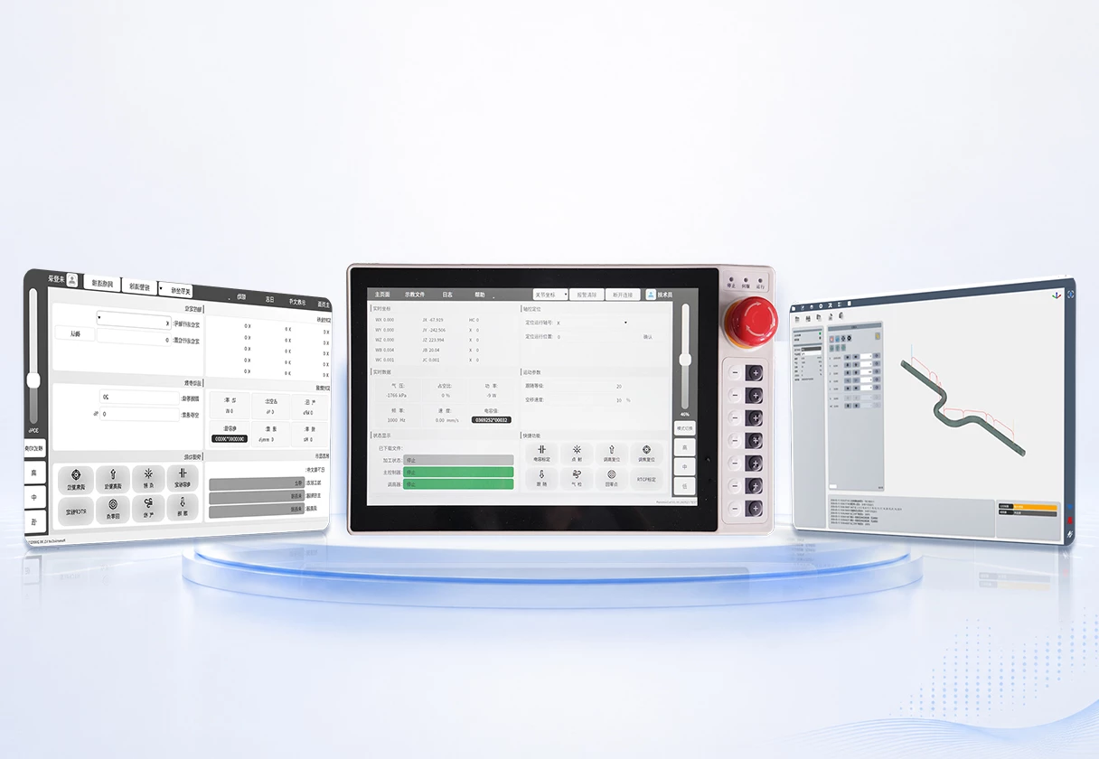
The AT series is equipped with control and programming/teaching functions for 3D laser processing.
Engineers can import workpiece models to extract cutting contours, plan paths, and verify 3D trajectories, while also handling on-site adjustments through a combination of manual teaching, online editing, and breakpoint positioning.
- 3D model import and cutting-contour preparation
- Toolpath planning and 3D trajectory display
- Offline programming with on-site teach-in
- Online program editing and breakpoint positioning
Alternate cutting with loading and unloading
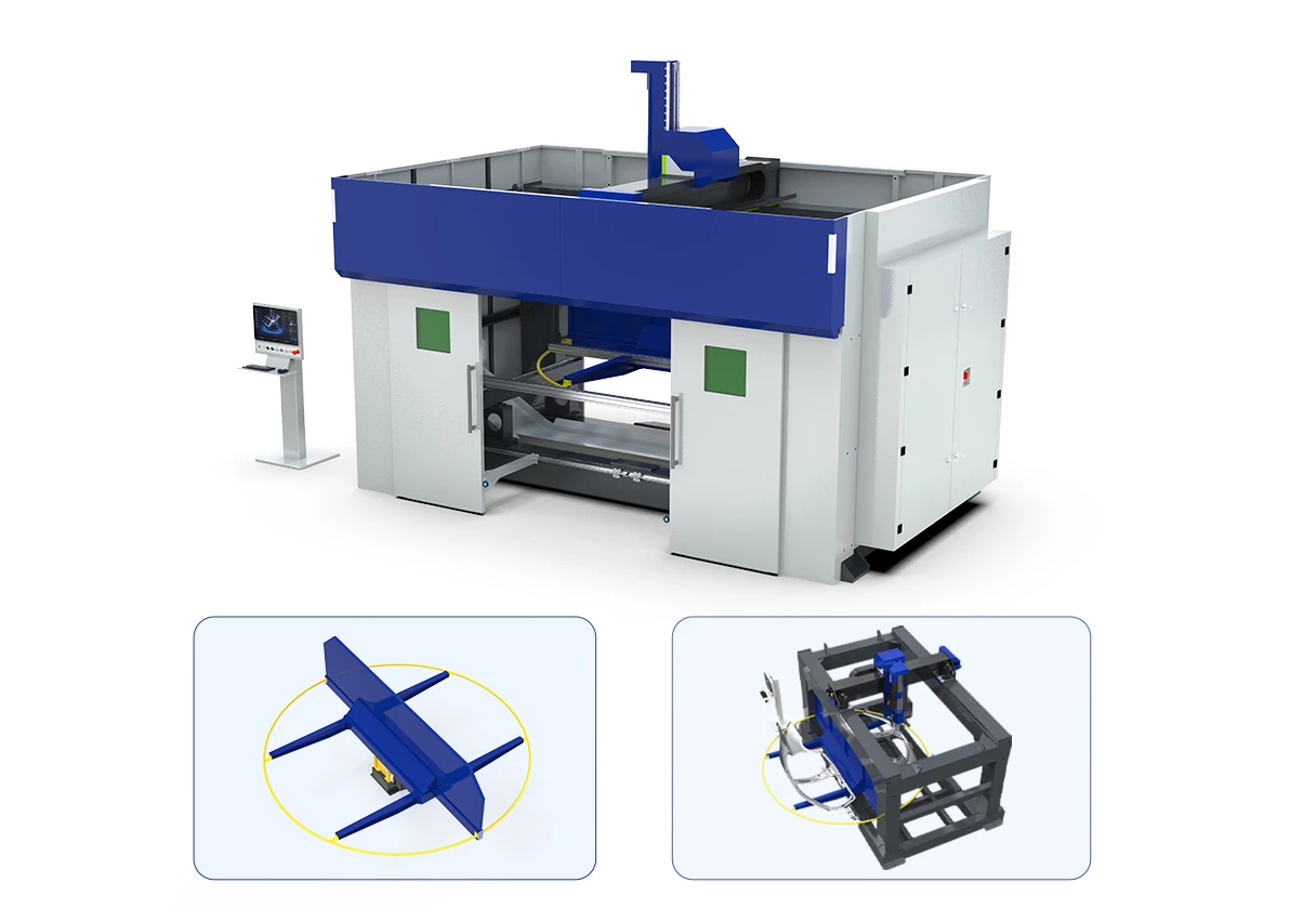
The AT3015 configuration with a rotary positioner uses two alternating stations. One station is used for cutting while the other is prepared for loading or unloading when the required safety separation and interlock conditions are met. After cutting, the positioner brings the next part into the processing area.
For repetitive batch production, this method can reduce machine waiting time between loading operations. Its effect on overall output depends on the cutting time per part, manual or automated loading time, fixture positioning and station-change timing.
Optional on AT3015. Suitability is assessed against the part, fixture and production workflow.
Cut02
Load / Unload
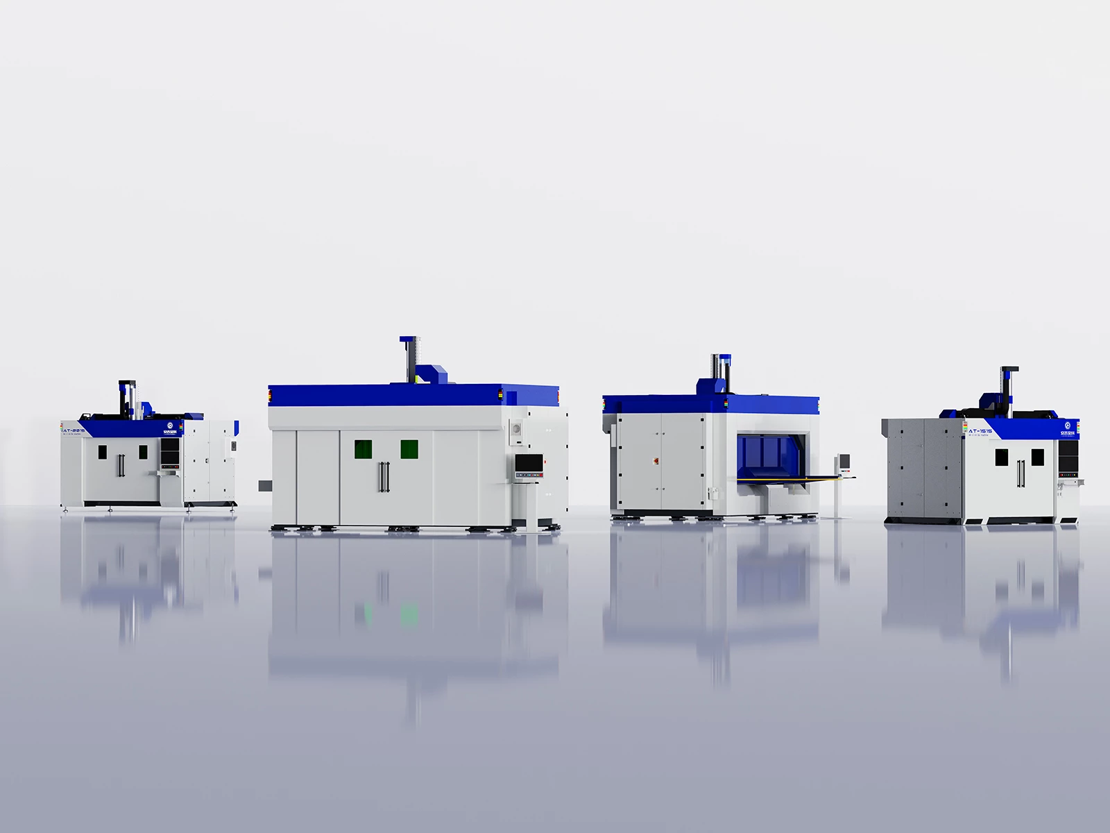
Select a model around your part and workflow
AT1515, AT2015 and AT3015 offer different working range. An optional AT3015 configuration with a rotary positioner serves production tasks that require two alternating stations. Select the model around part dimensions, fixture space and the loading method.
Small to medium hot-formed parts, stampings, housings and prototypes
Longer automotive parts, frames and mixed-model production
Long frames, trays and large formed structures
Repetitive batches with alternating cutting and loading stations
Laser power, core component brands, cutting head, positioner, material handling, exterior colors and branding can be configured for the project. The final usable working envelope and model selection depend on the part model, fixture and order-specific technical agreement.
AT2015 Technical Specifications
AT2015 shown as an example.
Overall dimensions are width × depth × height. Weight is approximately 5 t, excluding fixtures and auxiliary equipment. The 11 kW machine-power figure excludes the laser source and chiller and is not the total electrical demand of the complete system. Confirm the configuration and site power requirements in the technical agreement.
| Specification | AT2015 |
|---|---|
| X-axis travel | 2000 mm |
| Y-axis travel | 1500 mm |
| Z-axis travel | 700 mm |
| C-axis travel | ±360° |
| B-axis travel | ±130° |
| XYZ positioning accuracy | 0.08 mm |
| XYZ repeat positioning accuracy | 0.03 mm |
| BC repeat positioning accuracy | ±0.01° |
| XYZ maximum speed | 1000 mm/s |
| BC maximum speed | 400°/s |
| BC maximum angular acceleration | 3000°/s² |
| XYZ maximum acceleration | 6000 mm/s² |
| Worktable size | 2000 × 1500 mm |
| Overall dimensions W × D × H | 4000 × 2850 × 3400 mm |
| Machine weight | Approx. 5 t excluding fixtures and auxiliary equipment |
| Rated voltage | 380 V |
| Rated frequency | 50 / 60 Hz |
| Machine power excluding laser source and chiller | 11 kW |
Configure the machine for your parts and factory
The AT Series can be configured with laser power, core component brands, cutting head and peripheral equipment matched to material, thickness, part size and production cycle requirements. Fixtures, loading methods and operating direction are evaluated against the actual production workflow.
Distributors, system integrators and customers with consistent branding requirements can discuss machine colors, private-label logos, sheet-metal appearance and protective enclosures. Custom designs must also account for safety, maintenance access and installation conditions.
-
Processing
Laser Power, CoresEomponent Brards;Cutting Head,Cooling & Other Peripherals
-
Production flow
Fixtures, loading method and direction, and the AT3015 dual-station option
-
Appearance and branding
Colors, private-label logos, sheet-metal styling and protective enclosures
-
Site integration
Factory space, power, gas, fume extraction and maintenance access
Plan the machine position and production routes
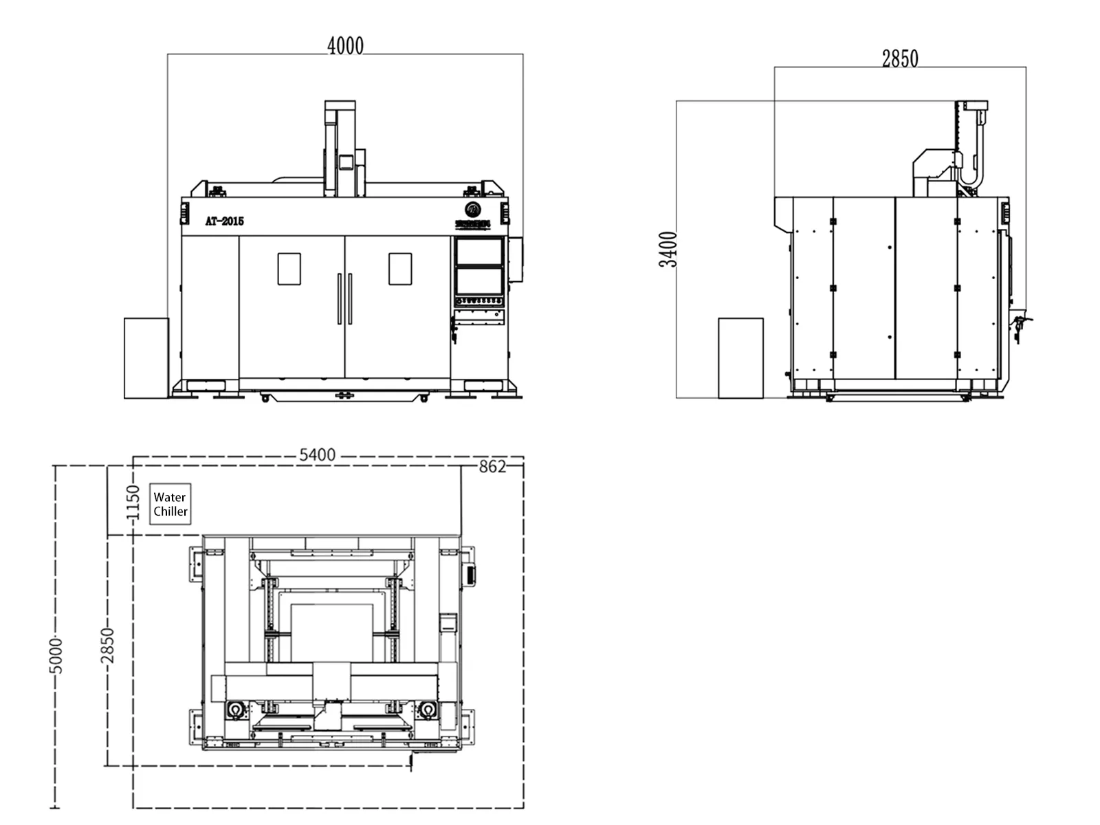
Before installation, plan the machine footprint, operator area, loading routes and maintenance access. Reserve space for the laser source, chiller, fume extraction, gas supply and electrical connections. We can discuss an installation layout based on the selected model and your factory conditions.
AT2015 overall dimensions are 4000 × 2850 × 3400 mm (width × depth × height), with a machine footprint of 4000 × 2850 mm. The current layout drawing recommends an installation area of approximately 5400 × 5000 mm. Final requirements depend on peripherals, material routes and the approved engineering drawing.
The installation-area illustration does not specify foundation load capacity. Machine foundations, lifting access and maintenance clearances must follow the approved engineering drawing.
AT2015 shown as an example.
- Machine W × D × H
- 4000 × 2850 × 3400 mm
- Recommended installation area
- 5400 × 5000 mm
Laser tube cutting machines
5 axis laser cutting machine
Review the documents behind your supplier
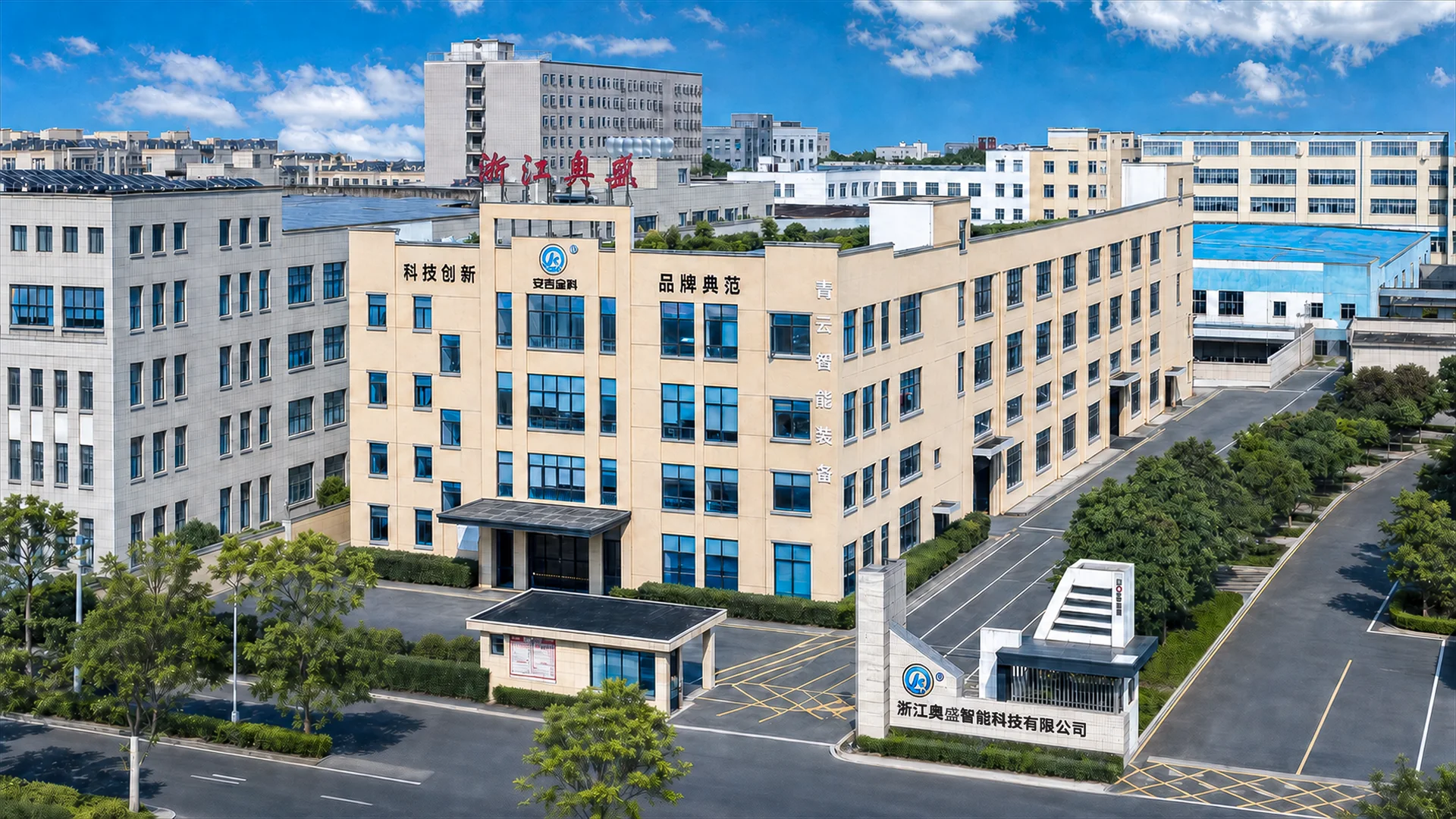
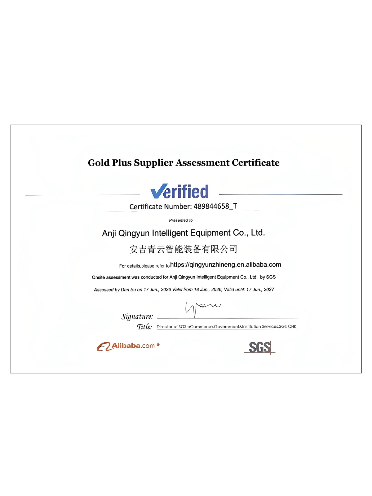
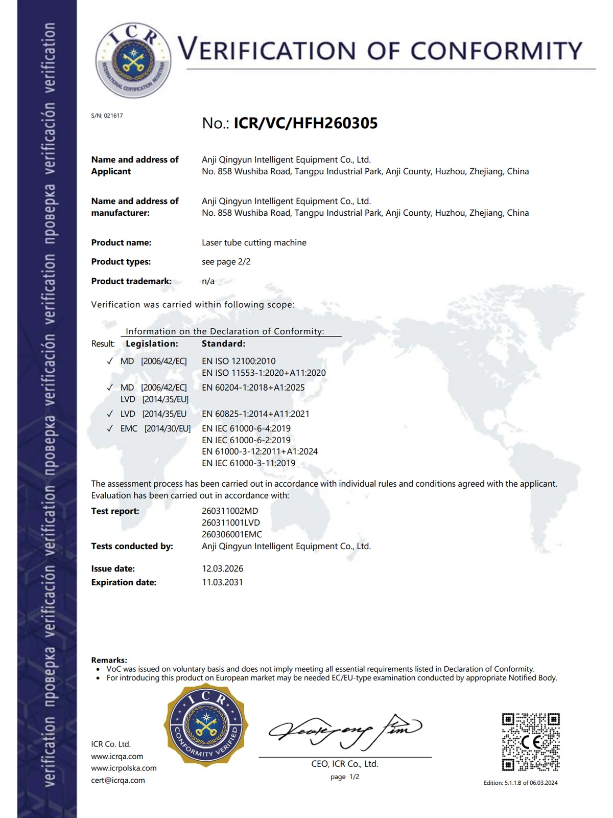
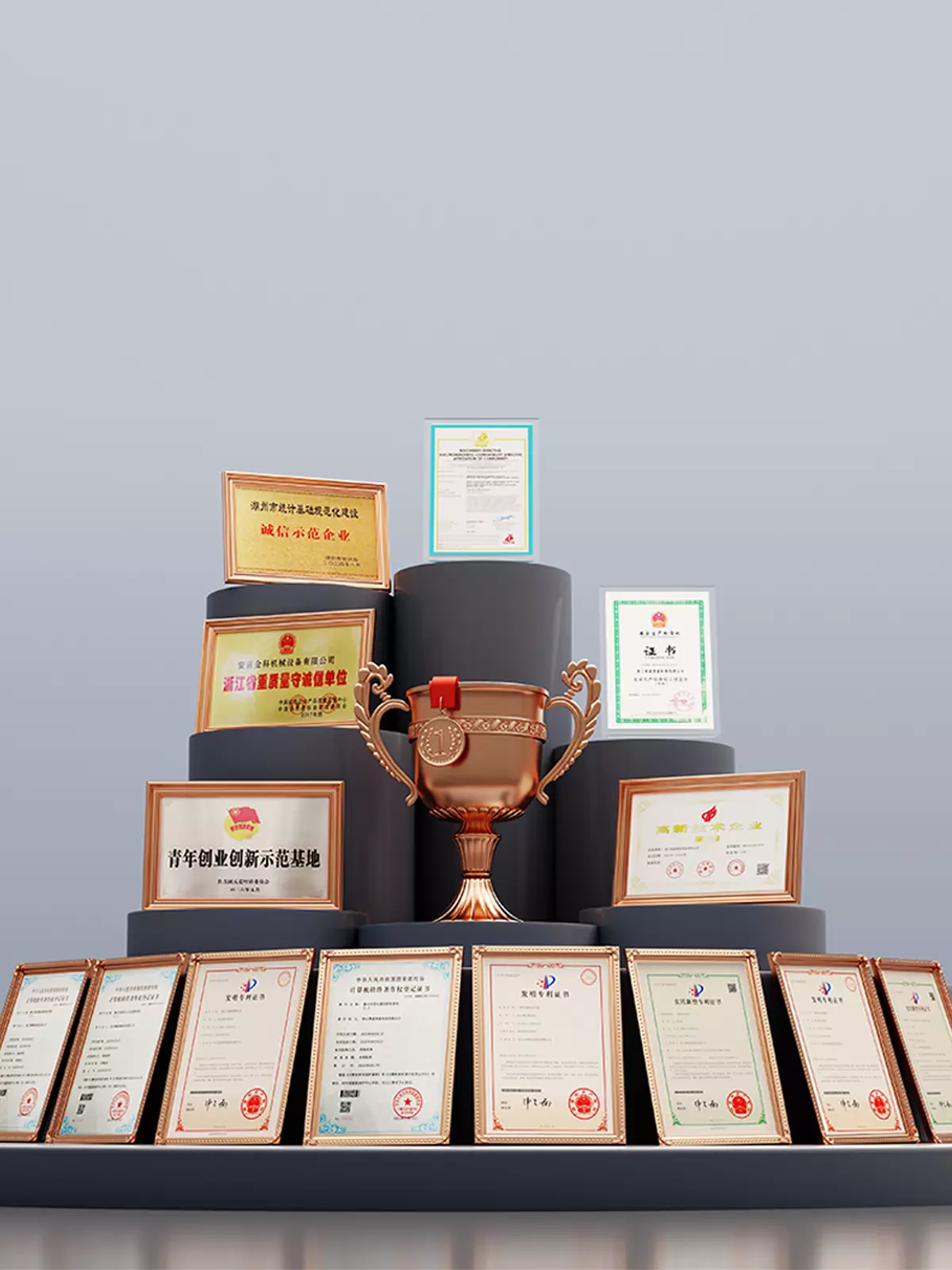
Our factory passed SGS factory audit, with CE certification for relevant products and ISO9001 QMS certification.
6S site management is fully applied. We rigorously control production, quality and product safety, offering stable & reliable products and services to worldwide clients.
Review supplier-assessment and conformity documents alongside the applicable product and model scope. Ask our team for the documents relevant to your proposed configuration.



Support from commissioning to long-term maintenance
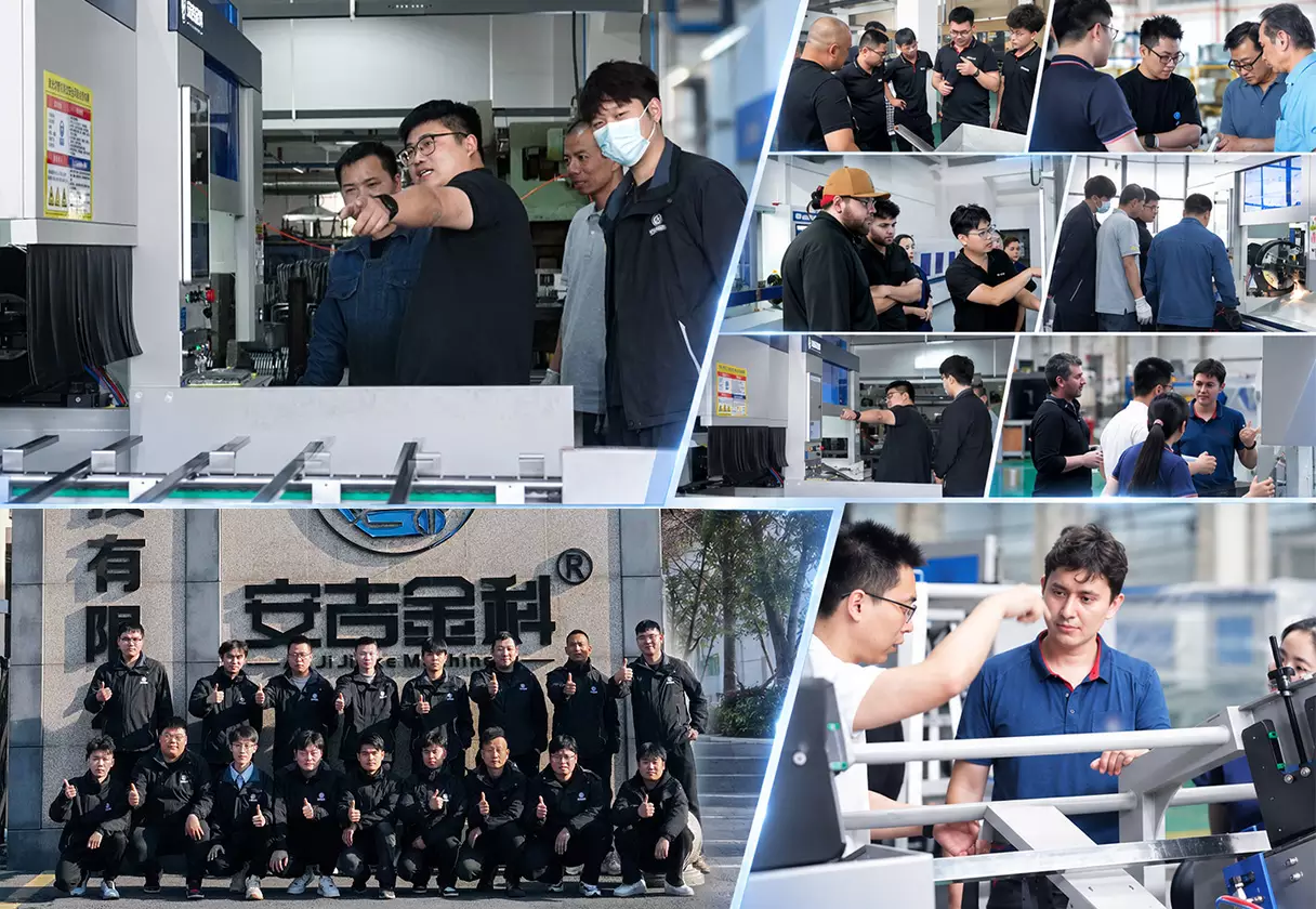
Equipment delivery is the start of the project. QINGYUN provides overseas customers with English installation manuals, operating videos and maintenance information, along with remote guidance for installation, commissioning and parameter setup. After production starts, customers can access online troubleshooting, technical support, operator and maintenance training, and supplies of wear parts, spare parts and consumables.
When a project requires it, engineer visits for installation or repair can be arranged subject to region, visas, site conditions and contract terms. Overseas distributors or local service partners may also provide support. We commit to an initial response to technical issues within 24 hours, first clarifying the issue and response plan, then providing remote support or arranging site service as appropriate.
Not a guaranteed repair time
- English manuals, operating videos and maintenance information
- Remote installation, commissioning and parameter guidance
- Online fault diagnosis and technical support
- Operator and maintenance personnel training
- Wear parts, spare parts and consumables
- On-site engineer installation or repair when required
- Support through overseas distributors or local service partners
- Initial response within 24 hours
AT Series Frequently Asked Questions
Discuss your actual parts, production requirements and factory conditions with our technical team.
Ask a Technical QuestionWhat are the differences between fixed gantry 5-axis equipment and robotic-arm laser cutting?
A fixed-gantry five-axis machine operates within a defined rectangular working area. More direct structural rigidity-to-motion relationship,suitable for repetitive cutting, hole-making and trimming tasks. A robotic arm offers more flexible orientations for multi-directional access, flexible layouts and coordination with other processes. The final selection should be evaluated based on workpiece model, cutting positions, fixtures, cycle time and on-site space.
Which parts are suitable for the AT Series?
It is suited to hot-formed and stamped parts, complex curved components, housings, trays, frames and other metal parts with contours or holes in different directions. Industry category alone does not determine suitability: material, thickness, part size, cutting locations and fixturing must be checked.
Can every three-dimensional part be cut directly?
No. Cutting-head access, fixture obstruction, deep recesses, reverse-facing contours, material reflectivity and part tolerances all affect the result. Provide a 3D model or sample so the technical team can assess toolpaths and interference.
How do I choose between AT1515, AT2015 and AT3015?
Start with the working area required by the part and fixture, then consider loading space, batch size and future part dimensions. If one station needs to be prepared while the other is cutting, assess the AT3015 with a dual-station rotary positioner. Station indexing does not add another simultaneous cutting axis.
Is axis positioning accuracy the same as finished-part cutting accuracy?
No. The final result also depends on part positioning, fixtures, material, thickness, laser power, cutting-head orientation, process settings, thermal effects and the programmed path. Sample cutting can verify dimensional accuracy and edge quality for the actual part.
What do you need for a process assessment and quotation?
Provide a STEP, IGES or other readable 3D model, together with material, thickness, annual or batch quantity, target cycle time, cut-quality requirements, loading method and factory electrical conditions. Samples, cutting videos and details of the current process are also useful.
Do you provide overseas installation and training?
Yes. QINGYUN provides English documentation, remote installation and commissioning, parameter setup, online diagnostics, and operating and maintenance training. Where necessary, site service or support from overseas distributors and local partners can be arranged according to contract and project conditions.
What is the warranty period?
The machine warranty is one year and the laser-source warranty is two years. Coverage, wear parts, on-site service and brand-specific terms are governed by the contract.
Is the dual-station rotary positioner standard on every model?
The configuration shown is an AT3015 option for alternating between cutting and loading stations. The configuration, fixture load and timing require a part-specific assessment. It is not a standard feature of AT2015.
Can colors, logos and key components be customized?
Machine colors, logos, sheet-metal styling, laser power and core components can be discussed. Our technical team will define a workable configuration around the process, site conditions and safety requirements.
How much installation space is needed?
Using AT2015 as an example, the machine measures 4000 × 2850 × 3400 mm, and the current drawing recommends an installation area of approximately 5400 × 5000 mm. Check the final engineering layout with peripherals, material routes and maintenance access included.