
What file format is used in laser cutting machines? How to choose DXF, SVG, PDF and STEP
Cut the two-dimensional part and prioritize confirming whether the device can import a 1:1 vector DXF. If the pattern is created in vector drawing software and the device software supports SVG, you can also directly submit the SVG. Engraved photos can be made using PNG or JPG. When encountering pipe wall openings, bevels, or slopes, first confirm whether the pipe cutting software supports STEP (.step or.stp) and whether these processing features can be identified from the 3D model. Purdue University Laser Cutting Document Guide · Angikinko A22-C Pipe Cutter Information
Select file format based on processing task
A path is needed to cut through. The software generates cutting trajectories along vector line segments and curves, and the outer edges, circular holes, and notches of the parts must have corresponding geometric profiles. Photo engraving is typically scanned line by line, pixel by pixel. Surface engraving lines can also follow vector paths, but the engraving process needs to be specified for this path in the software. University of Edinburgh Laser Document Preparation Guide · University of New South Wales Laser Cutting Guide
| Operation | File format | What to confirm before sending |
|---|---|---|
| Cut the profile, holes, and slots of a flat part | DXF or, if accepted, DWG | CAD file version, drawing units, and actual part dimensions |
| Cut sign outlines, lettering, or artwork | SVG, or DXF or AI if requested | Whether the software reads the vector paths and whether text needs to be converted to outlines |
| Cut a part from a PDF | PDF with vector paths | Whether the receiving software can read those paths. A scanned PDF typically contains only pixels. |
| Engrave a photo or an image with tonal detail | PNG or JPG | Whether the software imports it as a bitmap and whether the engraving area is the correct physical size |
| Cut a tube with wall openings, angled ends, or bevels | STEP, if supported | Check the tube profile, hole locations, and end features after import. Then review the machining preview. |
The same extension may also encounter version restrictions. For example, a laboratory guide from the Polytechnic University of Milan requires the submission of the AutoCAD 2000/LT2000 version of DXF. Before sending a document to the processor, ask the receiving software, file version and unit, and you can do one less export rework. Purdue University Formatting Instructions · Politecnico di Milano Document Delivery Guide
PDF or SVG can be opened, how can I tell if it can be cut?
Open the file with a vector editor and try selecting the outer edge or hole edge that needs to be cut separately. If you can view the nodes of this line, it means that there are editable paths in the file. If you select only the entire image at any point, you will be selected a bitmap object. If you put PNG into SVG or save the scan as PDF, the image will still remain in the file in pixel form. Finally, you need to preview the actual receiving software to confirm that these paths are indeed assigned as cuts. University of Edinburgh File Formatting Instructions · Inkscape Bitmap Tracing Guide
When you only have pictures, you can trace a simple sign first and then clean the path. Parts with assembly dimensions should be redrawn to their original dimensions. For example, a circular hole on a scan image may still appear round after tracing, but the aperture and hole center distance need to be checked upon delivery. The patterns look similar, so it’s impossible to verify the two sizes. Inkscape Bitmap Tracing Guide
When is STEP suitable for laser tube cutting?
See if the cut depends on the three-dimensional shape of the fitting. A square tube has holes on both adjacent sides, or the tube end has an inclined opening. The three-dimensional model can preserve which side the hole is on and which direction the inclined opening faces. If the workshop is programmed according to a two-dimensional expansion diagram, the DXF or DWG will be handed over according to the other party’s rules, and the reference plane and direction will be explained in the handover data. Taking only one front view of the model can easily miss the processing features of other sides.
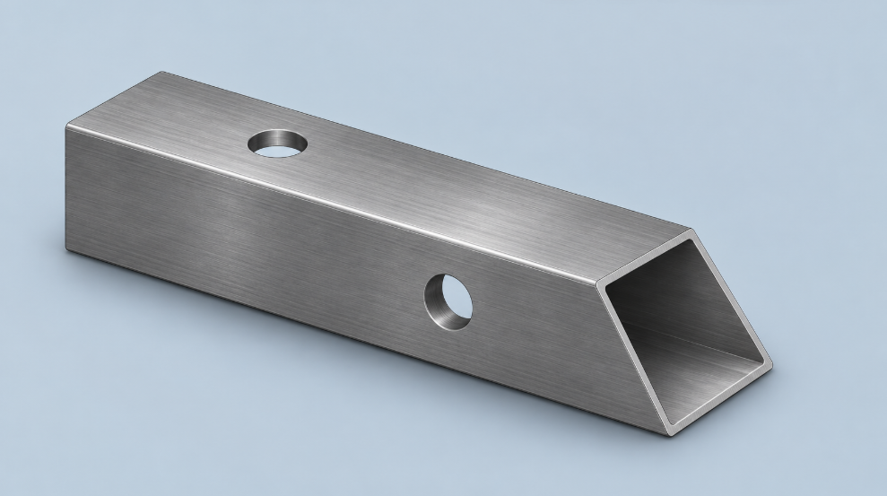
Taking Angekinco’s equipment as an example, the A16-C product page lists DWG and DXF, while the A22-C product page explicitly lists DXF, DWG, and STP. The A22-C’s operating instructions also list importing the 3D diagram and selecting the beveling process template as two actions. When passing pipe fittings with bevels, the side, direction, and angle of the bevel should be checked in the processing preview. A16-C Format Instructions · A22-C Format Instructions · A22-C Grooving Instructions
Check dimensions, outlines, and process layers after importing
- Measure a known size. For example, the outer edge on the drawing is 100 mm, and this edge is measured using a measuring tool after import. If the dimensions of the entire graph deviate by a fixed ratio, first check the exported units and imported ratios, and then modify the geometry. Even if the original image is drawn in a 1:1 ratio, the receiving software may still read it in different units. University of New South Wales Import Inspection Guide
- Check breakpoints and double lines. The outer and inner holes of the parts that need to be completely cut should form a closed profile. The outline has breakpoints, which may leave a small section of material connected. When two lines completely overlap, there may appear to be only one on the screen, but the software may generate two knife moves. Use the software’s weight check and closure check functions to verify. Harvard Laser Document Preparation Guide · UNSW Path Check Guide
- View the processing preview layer by layer. Cut, line, and engrave into different layers, and assign processes according to the receiving software or workshop template. During preview, confirm that the holes and outer edges are classified as cut, and the positioning lines or part numbers are classified as designated marking processes. Dimensional lines and frames can be placed in separate review drawings to avoid entering the cutting path. Purdue University Layers and Color Notes · Harvard University Layer Rules