
A12-CA Fully Automatic Bevel Tube Laser Cutter
Automatic rack loading for repeat batches of tube parts.
Ø20–120 mm round tubes
Up to ±45° bevels · 3000W reference configuration
Cut holes, slots, tube-end profiles and weld-preparation bevels on one machine.
Send Your Tube DrawingView specifications ↓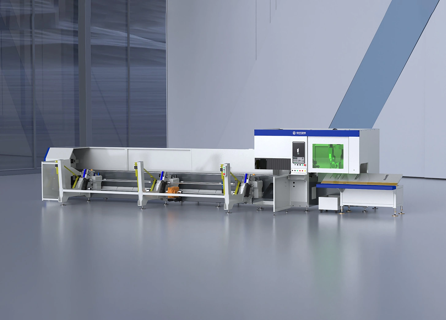
See the A12-CA at work
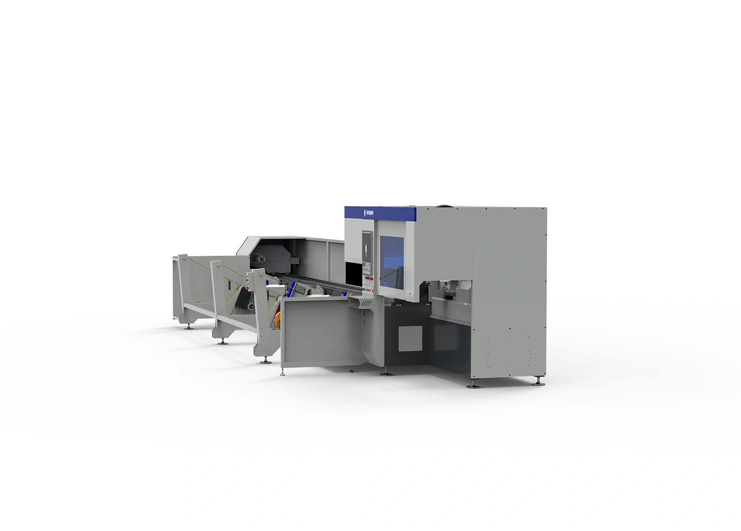
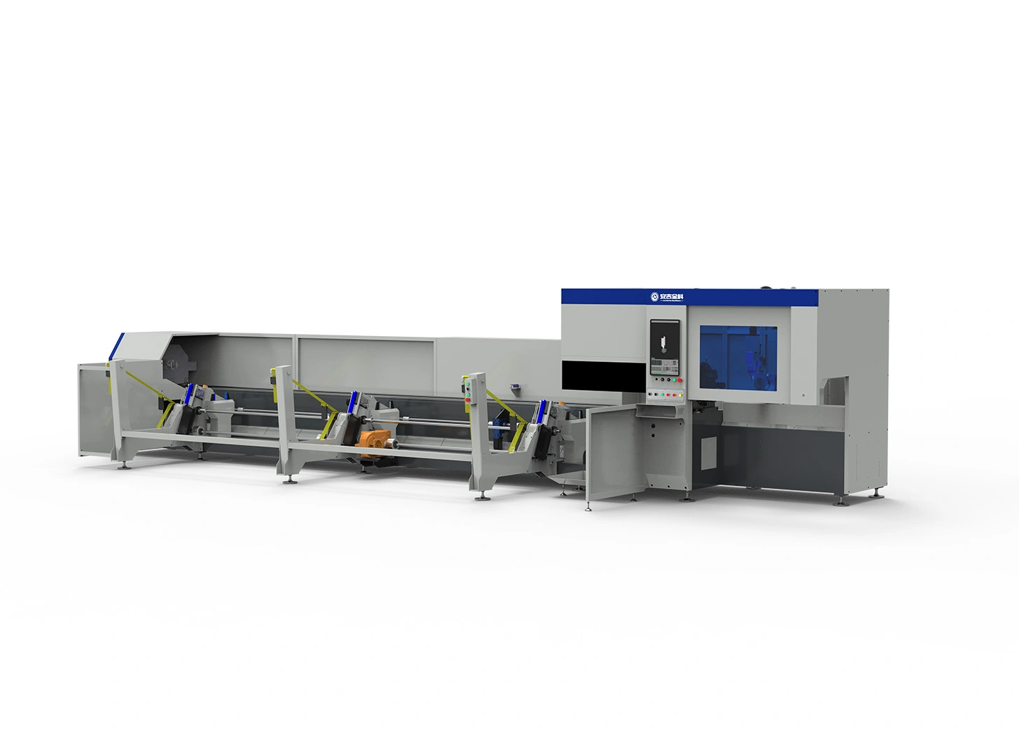
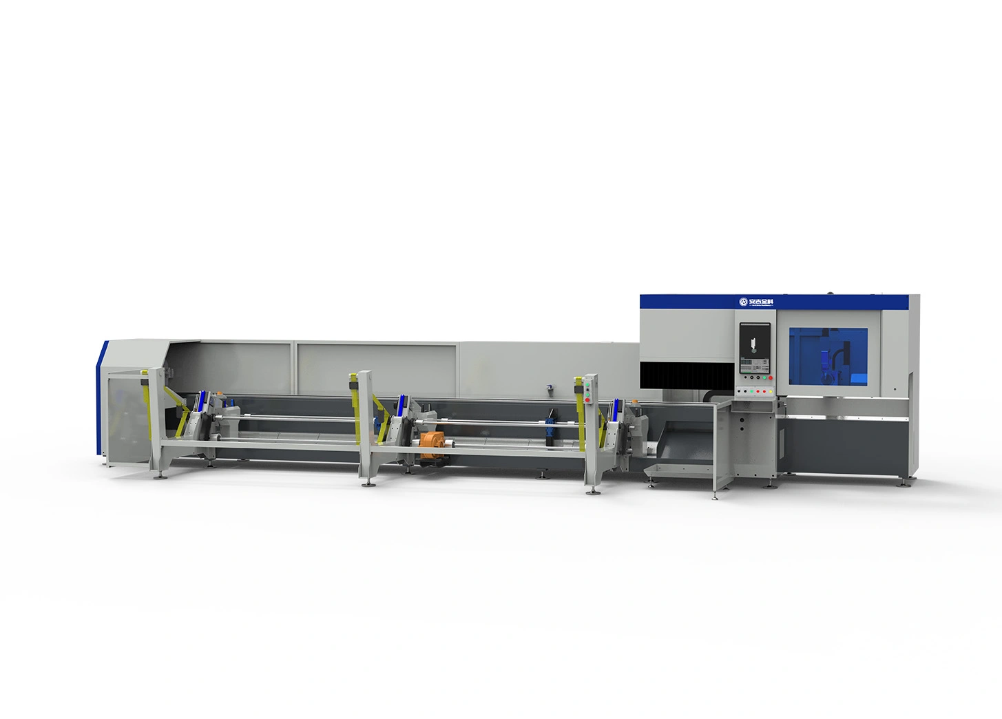
The A12-CA combines fully automatic loading with precision bevel cutting for repeat production of regular metal tube profiles. Once stock is on the rack, the machine loads and feeds each tube, then cuts holes, slots, end profiles and bevels. This reduces manual handling during processing and helps improve cutting accuracy.
The A12-CA 3000W bevel configuration handles round tubes Ø20–120 mm and square tubes from 20×20 to 120×120 mm, with bevels up to ±45°.
Ø20–120 mm Round tube range
±45° Maximum bevel angle
110 kg Reference chuck load
3300–6500 mm Stock length for automatic loading
Regular tube profiles.
Automatic loading for repeat batches.
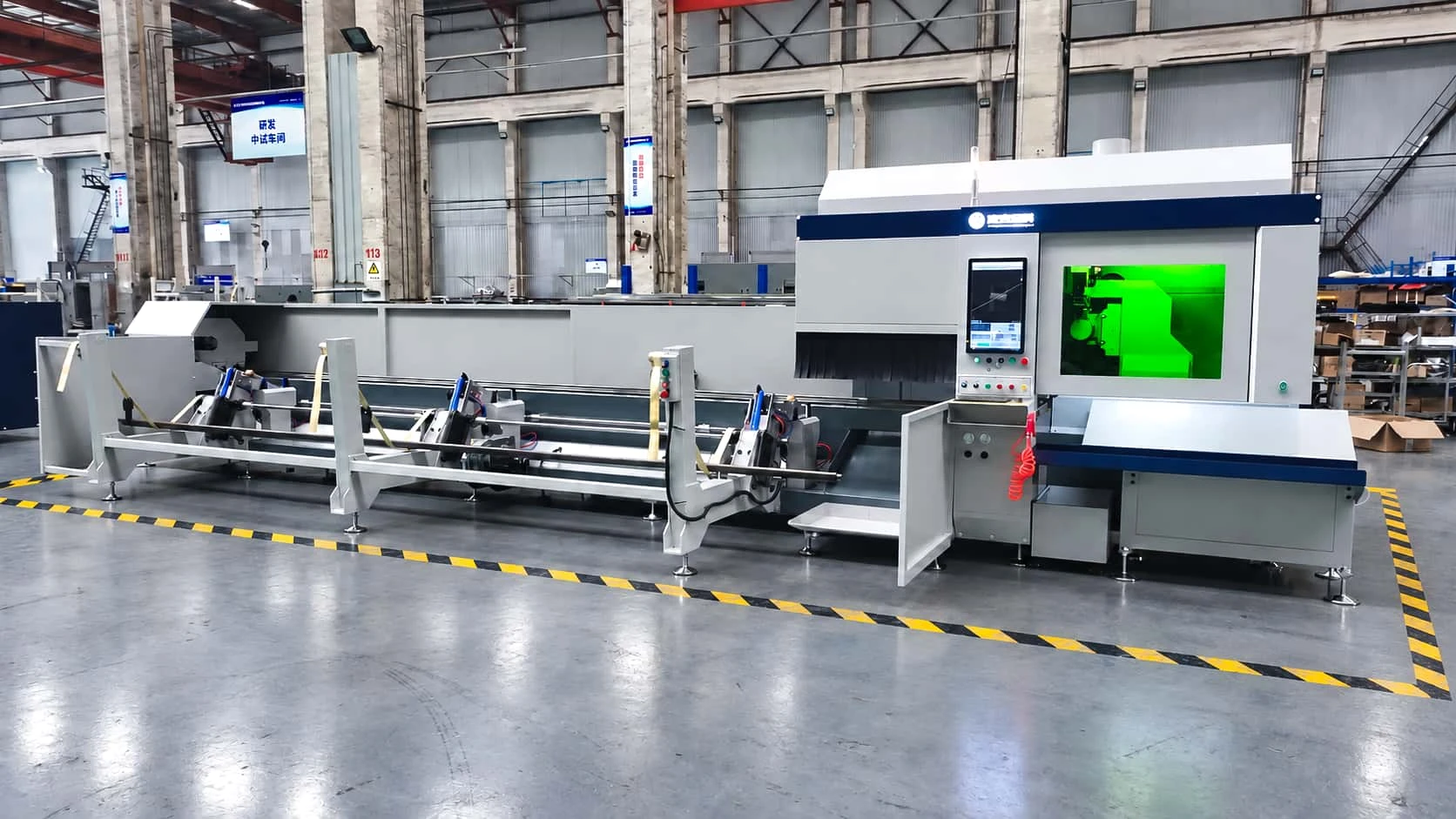
The automatic rack handles round, square and rectangular tubes. Stock length for the 3000W configuration is 3300–6500 mm. Operators replenish material and handle size changeovers; the machine loads and feeds tubes for continuous runs of the same profile.
Channels, angles, I-sections and other irregular profiles require manually assisted loading, with clamping matched to the cross-section. Automatic loading depends on the tube profile; irregular sections cannot simply use the standard loading cycle.
- Prepare stock on the rackReplenish material and change tube sizes
- Load and feed automaticallyRegular tubes enter the cutting cycle in sequence
- Clamp and cutCenter and clamp the tube, then cut
Watch automatic loading
Cut joint profiles in one setup
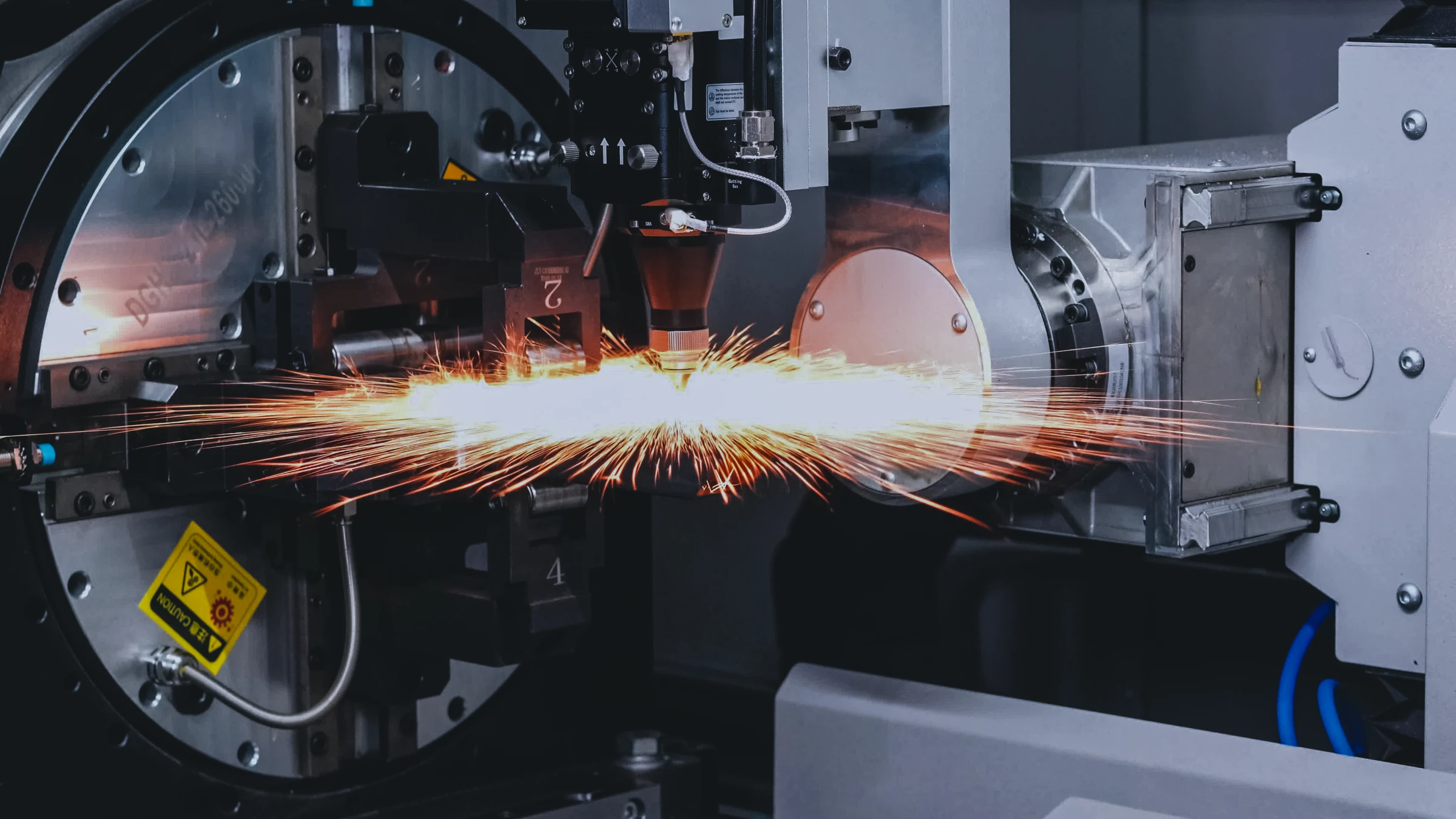
One machine cuts mounting holes, tube-end profiles and ±45° bevels for intersecting joints, mitered connections and welded brackets. Cutting these features on the tube reduces separate beveling, weld grinding and drilling after cut-off.
The autofocus cutting head works with the in-house XTUBECUT bus control system to display 3D toolpaths in real time. Profiles that meet chuck-clamping requirements can also be bevel-cut to suit the joint.
Clamping, centering and tube support
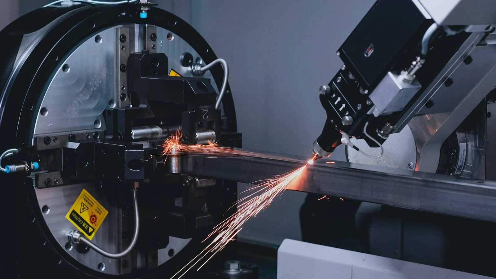
The pneumatic chucks clamp and center the tube in one action. Tube supports limit sag on long stock. Reference chuck load is 110 kg. Reduce rotation and motion settings as tube weight increases to keep feeding, clamping and cutting coordinated.
Use more of the tube near the chuck
Cutting-head overtravel and chuck avoidance reach material close to the clamped end. Reference dual-chuck remnant lengths are shown below.
| Cutting method | Reference remnant length |
|---|---|
| Straight cutting | ≥70 mm |
| Bevel cutting | ≥130 mm |
Actual remnant length depends on the profile, clamping method and part nesting. Zero-remnant cutting is possible for some parts, but must be confirmed with the actual tube and nesting layout.
From tube stock
to finished connections.
Application and sample images are illustrative. Use representative part drawings for test cuts to check holes, slots, bevels and fit-up.
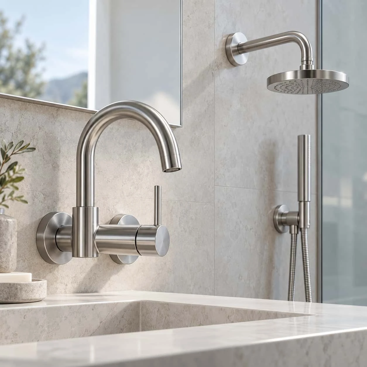
Bathroom and hardware tube fittings
Automatically feed regular tube profiles to cut holes and end contours.
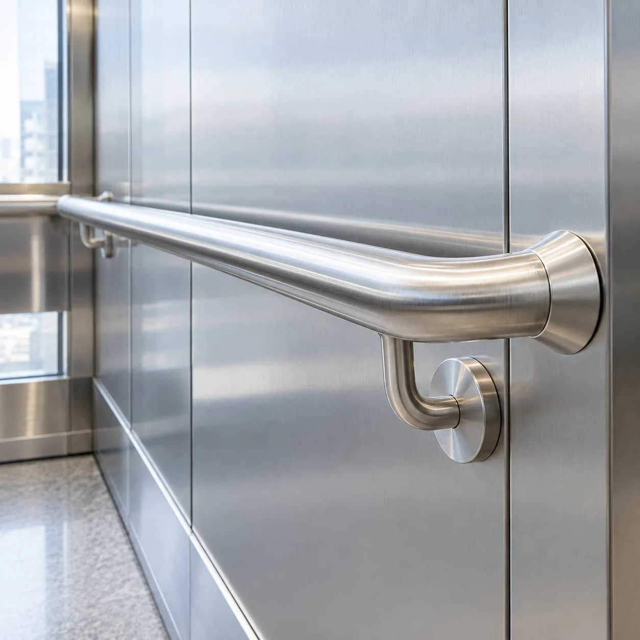
Elevator handrails and support tubes
Round tube joint contours, mounting holes and weld-preparation bevels.
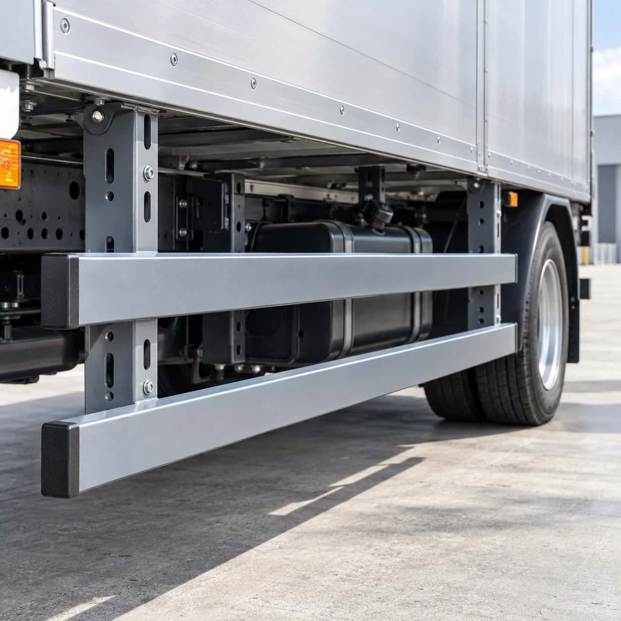
Transport equipment brackets
Square tube cut-off, connecting features and mounting holes and slots.
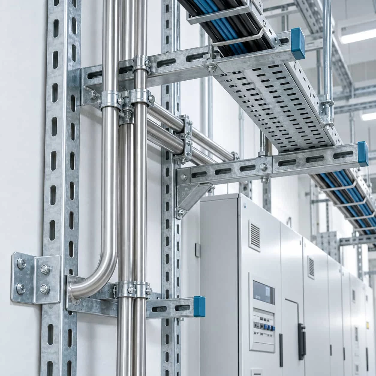
Power infrastructure components
Cut tubular supports to length and prepare their joints.
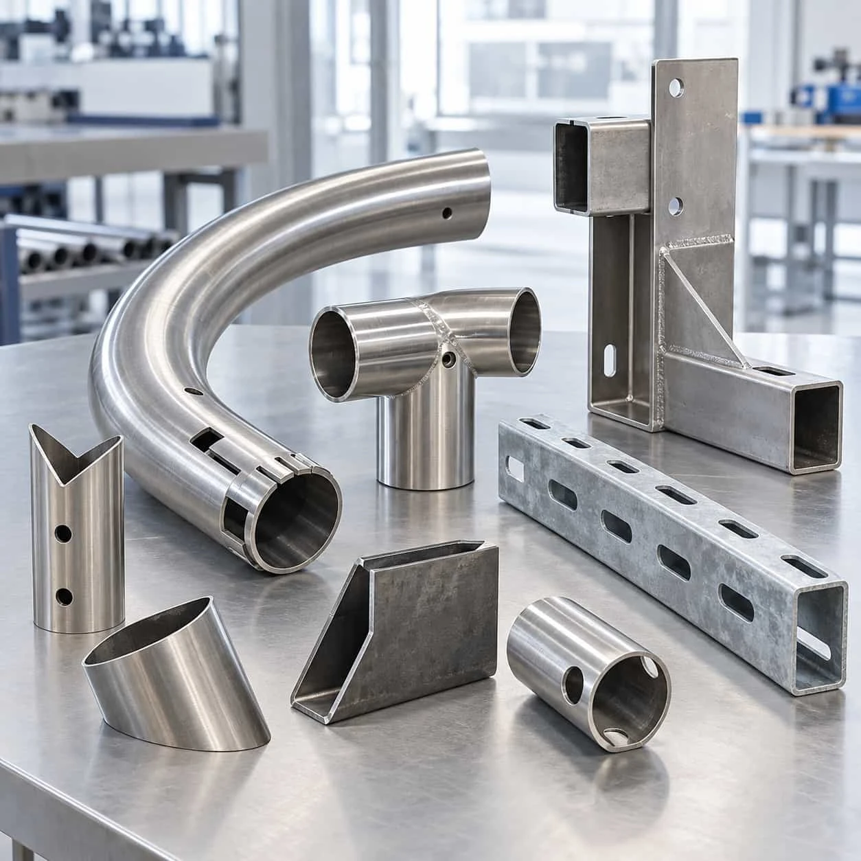
Batch tube processing
Check holes, slots, bevels and fit-up against each order.
Cutting range and specifications
| Item | Specification |
|---|---|
| Round tube outside diameter | Ø20–120 mm |
| Square tube size | 20×20–120×120 mm |
| Minimum actual wall thickness | ≥0.6 mm |
| Bevel angle | Up to ±45° |
| Chuck load | 110 kg |
| Automatically loaded stock length | 3300–6500 mm |
| Manually loaded stock length | 1000–7000 mm |
| Machine positioning accuracy | ±0.05 mm |
| Machine repeat positioning accuracy | ±0.03 mm |
| Maximum rapid traverse speed | 103 m/min |
| Maximum rotation speed | 200 r/min |
| Maximum acceleration | 15,000 mm/s² (approx. 1.5G) |
| Rated machine power | 17.8 kW (excluding laser source and chiller) |
| Machine weight | Approx. 4.5 t |
| Overall dimensions (L×W×H) | 9205×2681×1985 mm |
| Machine power supply | 380 V, three-phase, 50/60 Hz |
Motion figures are machine maxima and should be adjusted as tube weight increases. Positioning accuracy is a machine specification; finished-part tolerance also depends on stock, clamping and process settings. Confirm the footprint against the selected loading rack and site layout.
Match the process to material and wall thickness
These figures are reference capacities for typical 3000W operating conditions. Check tube size, wall thickness, assist gas and bevel angle together when selecting a process.
| Material / assist gas | Straight-cut wall thickness | Bevel-cut wall thickness |
|---|---|---|
| Stainless steel, carbon steel / air or nitrogen | ≤5 mm | 3.5 mm |
| Aluminum alloy / air or nitrogen | ≤4.5 mm | 3.2 mm |
| Carbon steel / oxygen, tube inside diameter >50 mm | ≤12 mm | 8.5 mm |
Minimum tube diameter, maximum wall thickness and maximum bevel angle are not a single guaranteed combination. Send your usual tube sizes and joint drawings so we can match laser power and process settings to the job.
Choose semi-automatic or fully automatic loading
| Comparison | A12-C Semi-Automatic | A12-CA Fully Automatic |
|---|---|---|
| Loading method | Operators arrange tubes on the rack; the machine feeds them automatically | The rack automatically loads and feeds regular tube profiles |
| Production fit | Different batches organized by the operator | Higher-volume runs of bundled stock with the same regular profile |
| 3000W round tube range | Ø15–120 mm | Ø20–120 mm |
Select either model according to tube shape, wall thickness, batch size and how stock is supplied on site. Minimum round-tube diameter is 15 mm for A12-C and 20 mm for A12-CA. Use the specifications for each model’s selected configuration.
Explore A12-C semi-automatic feedingFrom test cutting to delivery
Anji Qingyun Intelligent Equipment Co., Ltd. operates a 50,000 m² production site and installs more than 100 machines each year. We review drawings, run sample cuts and advise on layout to help confirm loading, clamping and cutting options.
Delivery includes operating instructions, wiring and pneumatic diagrams, and consumables information. Overseas projects receive English documentation, remote installation and commissioning support, operator training and spare-parts support. Technical requests receive a response within 24 hours; on-site service is arranged by project. The machine has a one-year warranty and the laser source a two-year warranty, subject to the contract.
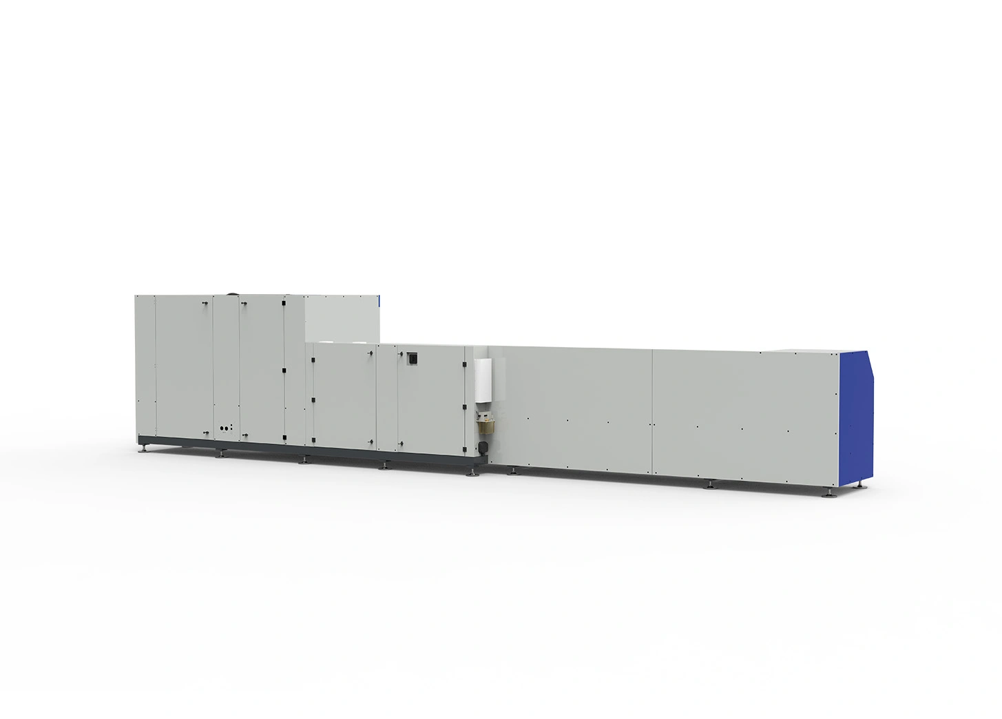
This configuration includes dust-extraction ports. The extraction unit is optional and matched to the project.
At a furniture factory in Vietnam
Review our
supplier documentation
The factory has passed an SGS assessment and holds ISO 9001 quality management certification. CE documentation is available for applicable products.
We use 6S workplace management to control production, quality and product safety and support consistent equipment and service delivery.
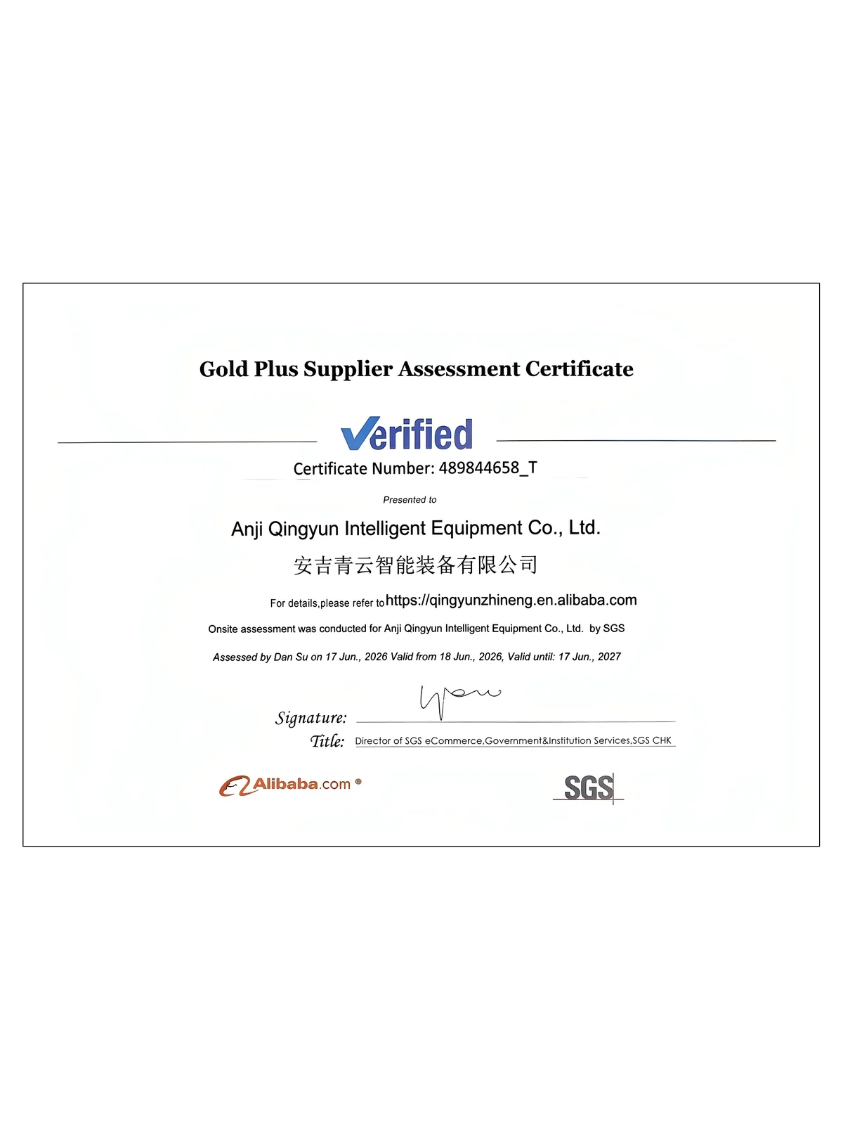
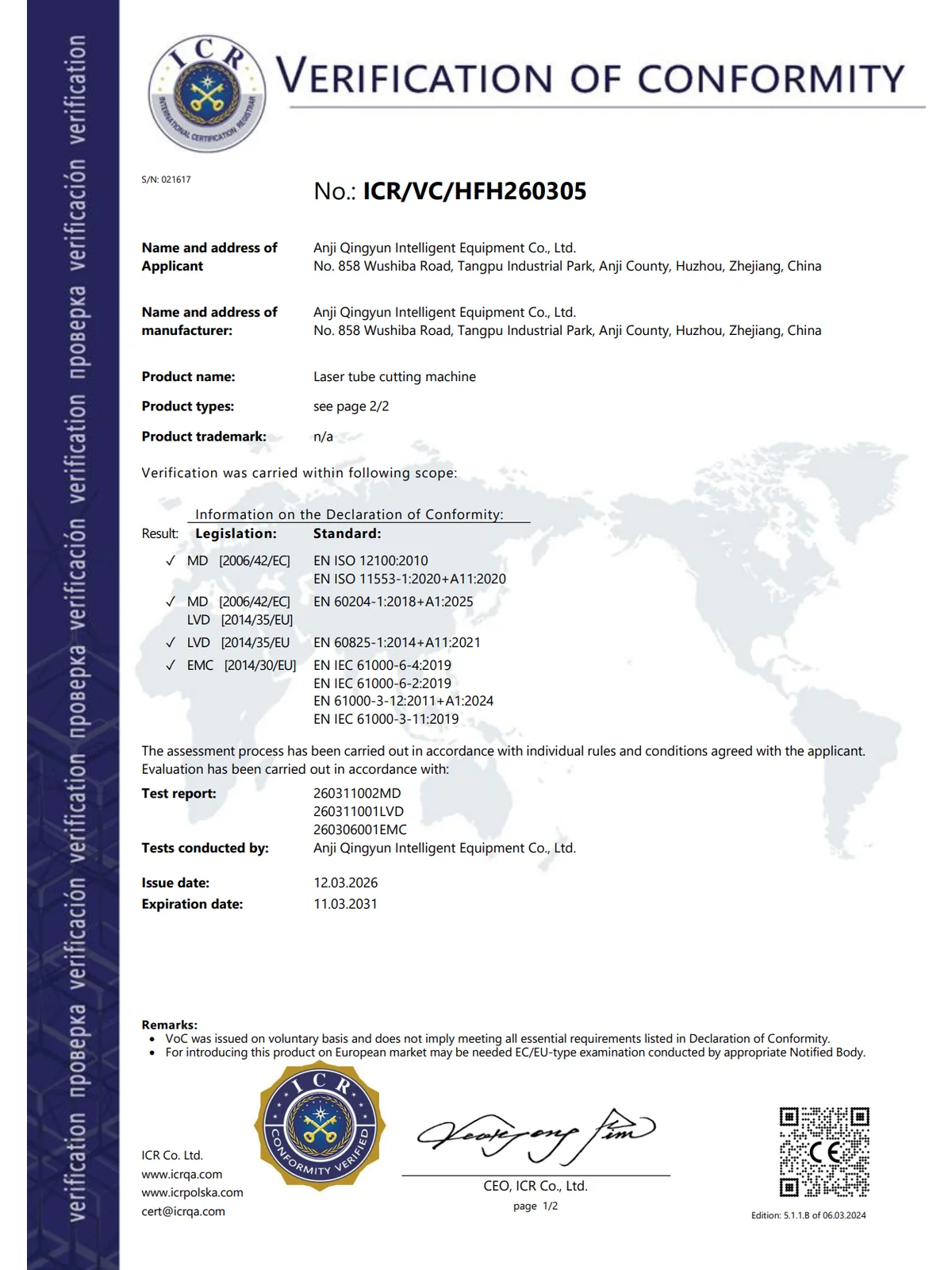

Review supplier assessments and conformity documents against the specific product and model. Ask our team for documents that apply to your intended configuration.
Questions before choosing a configuration
Check loading, stock dimensions and joint requirements against your actual orders.
Does fully automatic loading include finished-part sorting?
Here, fully automatic refers to loading from the rack and feeding the tube. Part support, collection and sorting are configured separately according to finished length and production flow.
Can this configuration process round tubes below 20 mm?
The specified lower limit is 20 mm. For smaller tubes, compare other models and confirm wall thickness and loading requirements.
Will automatic loading work after a profile change?
Round, square and rectangular tubes within the specified range can use automatic loading. Irregular profiles require manual assistance and a check of the cross-section and clamping conditions.
Request an A12-CA configuration and test cut
Send the material, cross-section, wall thickness, stock length, a representative part drawing and batch size. We can recommend the loading setup, arrange a test cut and prepare a quotation.
Send Drawings for a Test Cut