
A22-C tube
laser cutter
220 mm tube capacity. Up to ±45° bevels. Semi-automatic feeding.
Prepare welded tube parts, machine frames and structural components with dual-chuck remnant control.
Send Your Tube DrawingView specifications ↓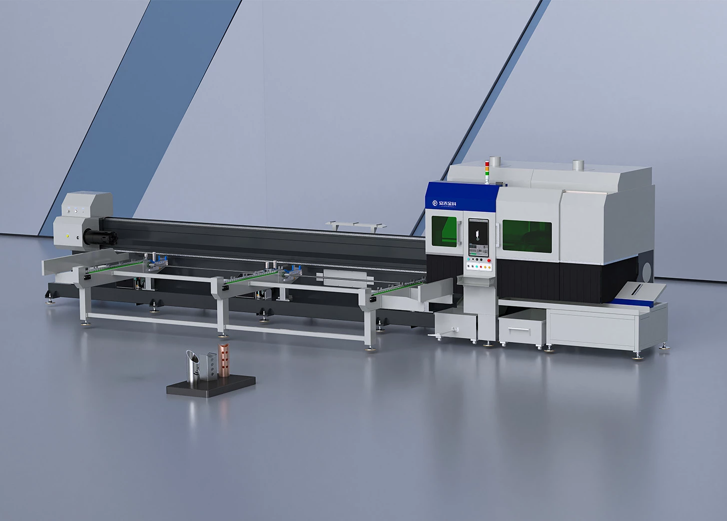
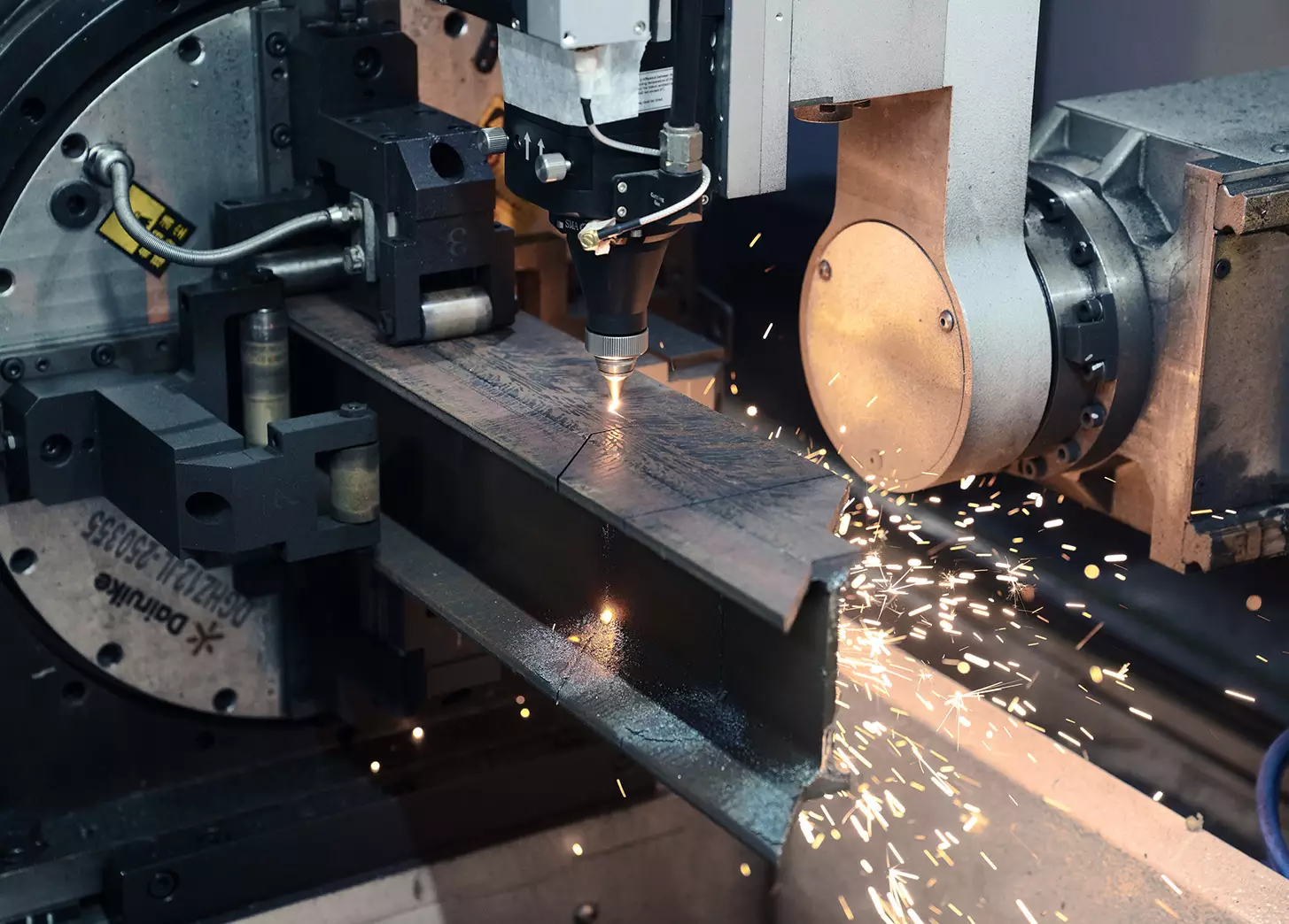
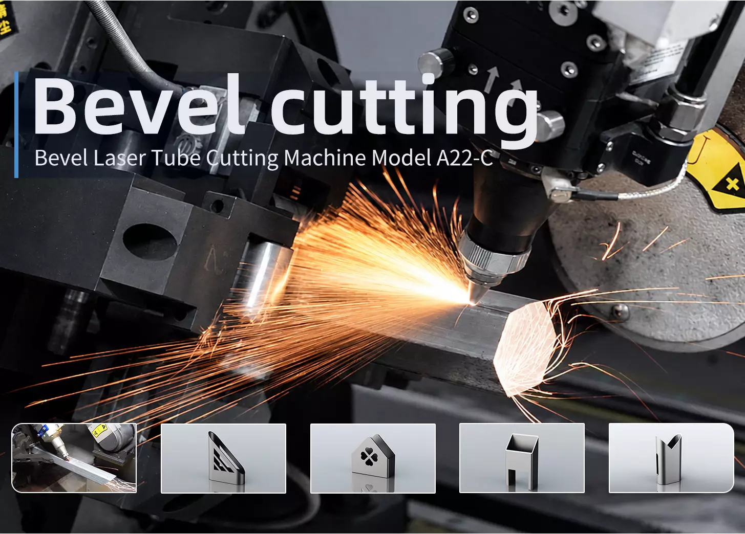
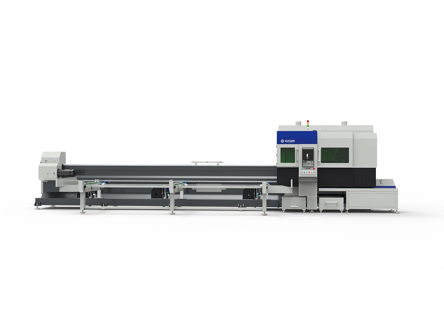
See the A22-C at work.
The A22-C combines semi-automatic feeding, bevel cutting up to ±45°, and dual-chuck remnant control for round tubes, square tubes, and profiles. It is designed for welded tube parts, machine frames, and structural components.
The 3000W configuration processes round tubes from Ø20 to 220 mm and square tubes from 20 × 20 to 220 × 220 mm. Chuck load capacity is 260 kg. Laser power and machine options can be matched to the material, wall thickness, and production volume.
Ø20–220 mmRound tube range
20–220 mmSquare tube side length
260 kgChuck load capacity*
3000WReference configuration
Stage the tubes.
Let feeding follow.
The operator places tubes on the staging rack, and the machine automatically feeds each tube to the chuck clamping position. Tubes do not need to be loaded into the chuck one by one. Wide/narrow-side detection helps orient rectangular tubes during feeding.
Wide/narrow-side detection helps orient rectangular tubes during feeding. Self-centering pneumatic chucks automatically center and clamp the tube.
Standard tubes use the semi-automatic process. Non-standard profiles require manual assistance according to their shape.
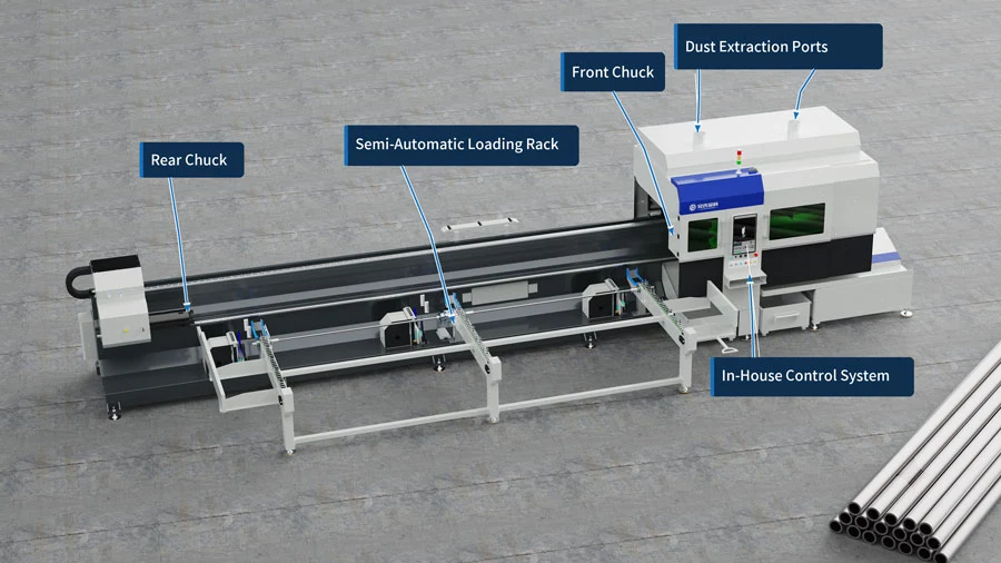
Watch the A22-C product film in a new window.
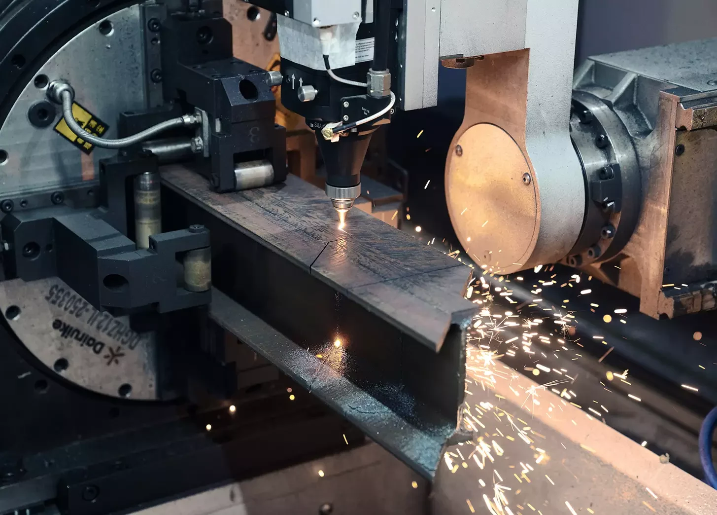
Bevels for
the next joint.
Cuts bevels up to ±45°, including V- and Y-grooves for welding. When the tube profile and chuck clamping conditions are suitable, the machine can cut mitred and intersecting joints for close, gap-free tube fit-up.
Profiles, holes, slots, mitres, and bevels are completed in one programming workflow, reducing part transfers and subsequent manual finishing.
Round, square and rectangular tubes are supported. Channels, angles, I-beams and oval tubes must meet the clamping requirements.
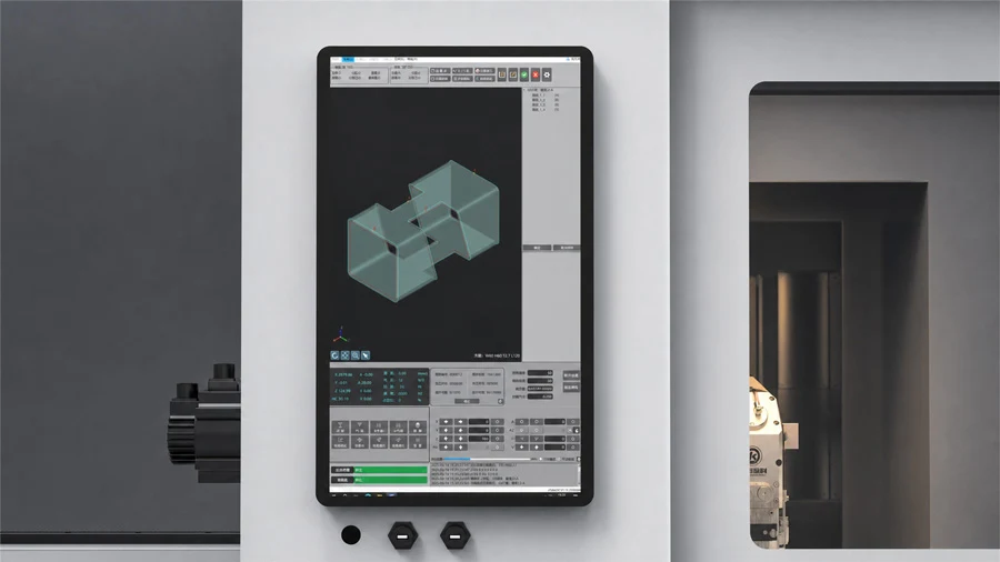
See the cutting path
XTUBECUT displays the 3D cutting path for checking part profiles and the cutting sequence.
Adjust focus automatically
The focus adjusts to the cutting task, reducing manual focus adjustment.
Compare the remnant.
Chuck coordination and cutting-head clearance allow cutting closer to the clamping end. Choose a process to compare the reference modes.
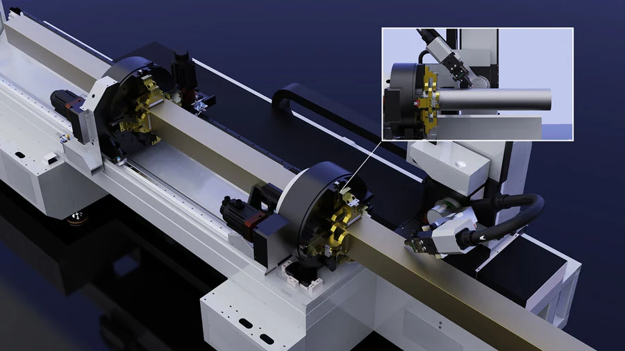
Front chuck only>170 mm
Dual-chuck clamping>145 mm
Zero-tailing mode*>5 mm
*For suitable tubes and nesting layouts. “Zero-tailing” does not mean a guaranteed 0 mm remnant.
| Clamping / Cutting Mode | Straight-Cut Reference | Bevel-Cut Reference | Notes |
|---|---|---|---|
| Front chuck only, with remnant | >170 mm | >400 mm | Single-chuck clamping |
| Dual-chuck clamping, with remnant | >145 mm | >295 mm | Dual-chuck clamping |
| Dual-chuck zero-tailing mode | >5 mm | >5 mm | For suitable tubes and nesting layouts |
Actual remnant length depends on the tube profile, clamping method, nesting layout, and straight or bevel cutting process. The values are references for the stated operating modes and do not guarantee the same remnant length for every part.
From tube to assembly.
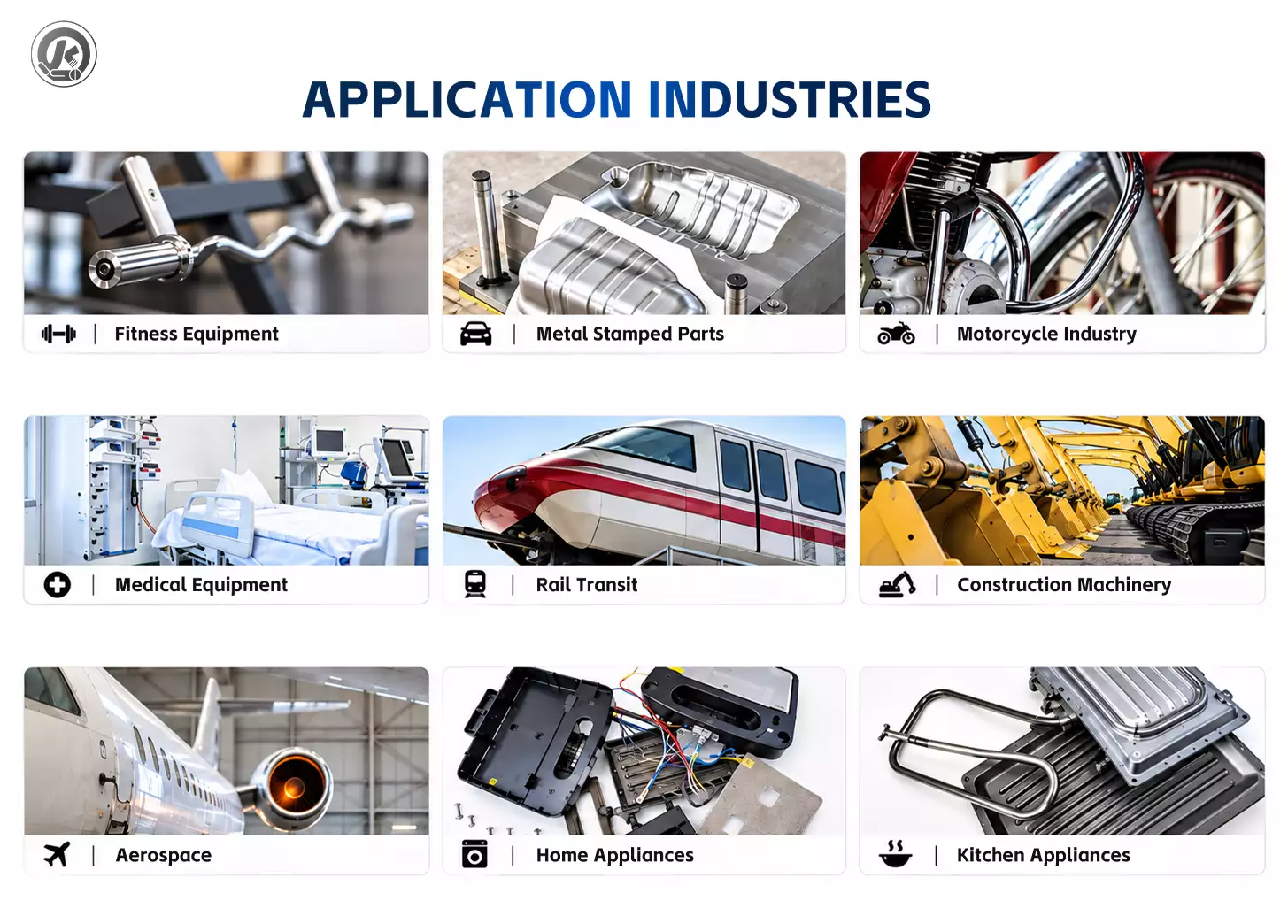
Explore typical parts and joint details. Application images are illustrative; final processing suitability is confirmed from your drawing.
Scroll to explore applications
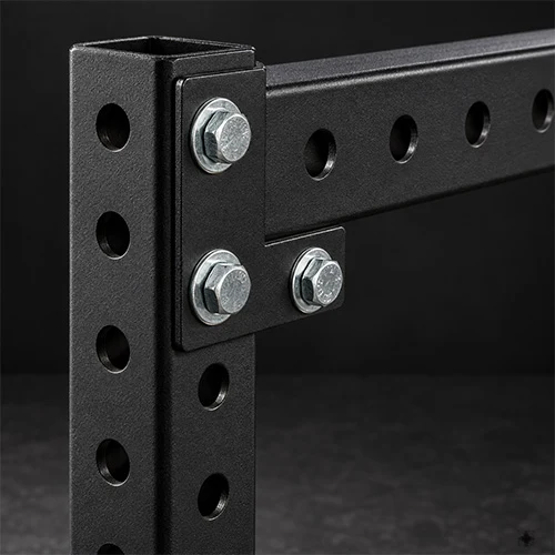
Structural fabrication
Frames, brackets, trusses and guardrails. Cut profiles, holes, slots and pre-weld bevels.
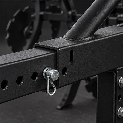
Agricultural machinery
Chassis tubes, booms and guards. Prepare heavier tubes and their joining features.
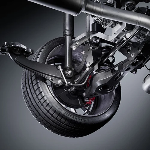
Transport equipment
Frame tubes, crossmembers and supports. Repeat profiles and prepare intersecting joints.
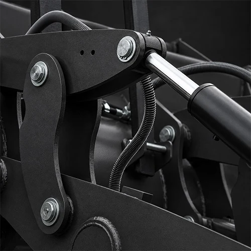
Industrial equipment
Skids, machine frames and tubular structures. Process larger profiles and pre-weld bevels.
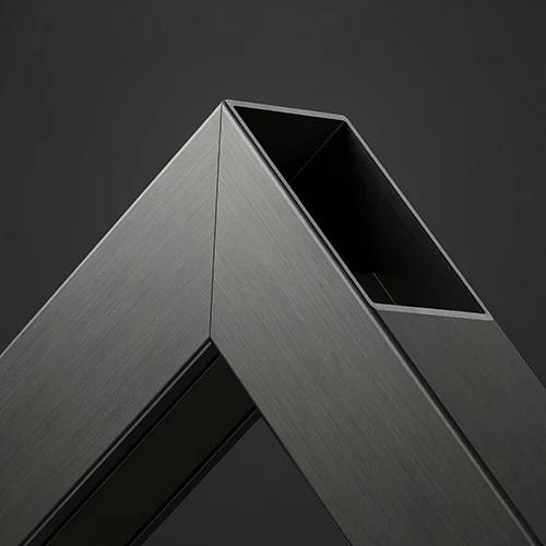
Frame joints
Illustrative mitred tube joint. Confirm your profile and fit-up requirements with a sample test cut.
Know the working range.
The figures below apply to the 3000W configuration with a top cover. Final delivery follows the confirmed configuration and drawings.
| Item | A22-C Reference | Notes |
|---|---|---|
| Reference Laser Power | 3000W | This page uses the covered reference configuration; other power levels are available by project |
| Round Tube Range | Ø20–Ø220 mm | Outside diameter; see the cutting table below for wall thickness |
| Square Tube Range | 20 × 20–220 × 220 mm | Side length; see the cutting table below for wall thickness |
| Minimum Practical Wall Thickness | ≥0.6 mm | Subject to material, tube profile, and clamping conditions |
| Other Profiles | Confirm Against Drawing | Confirm the profile, weight, and clamping method |
| Standard Feed Length | 3300–6100 mm | Range for standard tubes on the staging rack |
| Manual Loading Length | 1000–7000 mm | Requires suitable support and material handling |
| Maximum Rapid Speed | 100 m/min | Reduce motion settings as tube weight increases |
| Maximum Acceleration | 12,000 mm/s², approx. 1.2G | Machine motion parameter |
| Maximum Rotation Speed | 130 r/min | Reduce motion settings as tube weight increases |
| Machine Positioning Accuracy | ±0.05 mm | Machine accuracy; finished parts are also affected by material and process conditions |
| Repeat Positioning Accuracy | ±0.03 mm | Machine repeat-positioning reference |
| Bevel Angle | Up to ±45° | Subject to tube profile, clamping, and wall thickness |
| Chuck Load Capacity | 260 kg | Subject to total clamped weight and support arrangement |
| Reference Machine Dimensions | 9828 × 2986 × 2509 mm | Covered reference configuration; final dimensions follow the configuration drawing |
| Reference Machine Weight | Approx. 5.5 t | Confirm shipping weight from the final configuration |
| Reference Power Supply | 380 V, 3-phase, 50/60 Hz | Confirm against the electrical conditions at the destination |
*Chuck capacity depends on total clamped weight and support arrangement. Machine accuracy is not a guarantee of finished-part accuracy.
Match material and gas.
The minimum practical wall thickness is 0.6 mm. Typical thickness references are shown below. Actual cutting capacity depends on the material, assist gas, tube profile, and required cut quality.
| Material / Assist Gas | Typical Straight Cut | Typical Bevel Cut | Key Conditions |
|---|---|---|---|
| Stainless or Carbon Steel / Air or Nitrogen | ≤5 mm | 3.5 mm | Confirm the material grade and required cut quality |
| Aluminum Alloy / Air or Nitrogen | ≤4.5 mm | 3.2 mm | Confirm the alloy, surface condition, and cut quality |
| Carbon Steel / Oxygen | ≤12 mm | 8.5 mm | The reference configuration requires a tube ID greater than 50 mm |
For thicker material or higher output requirements, select another laser power level with the corresponding configuration.
Support beyond delivery.
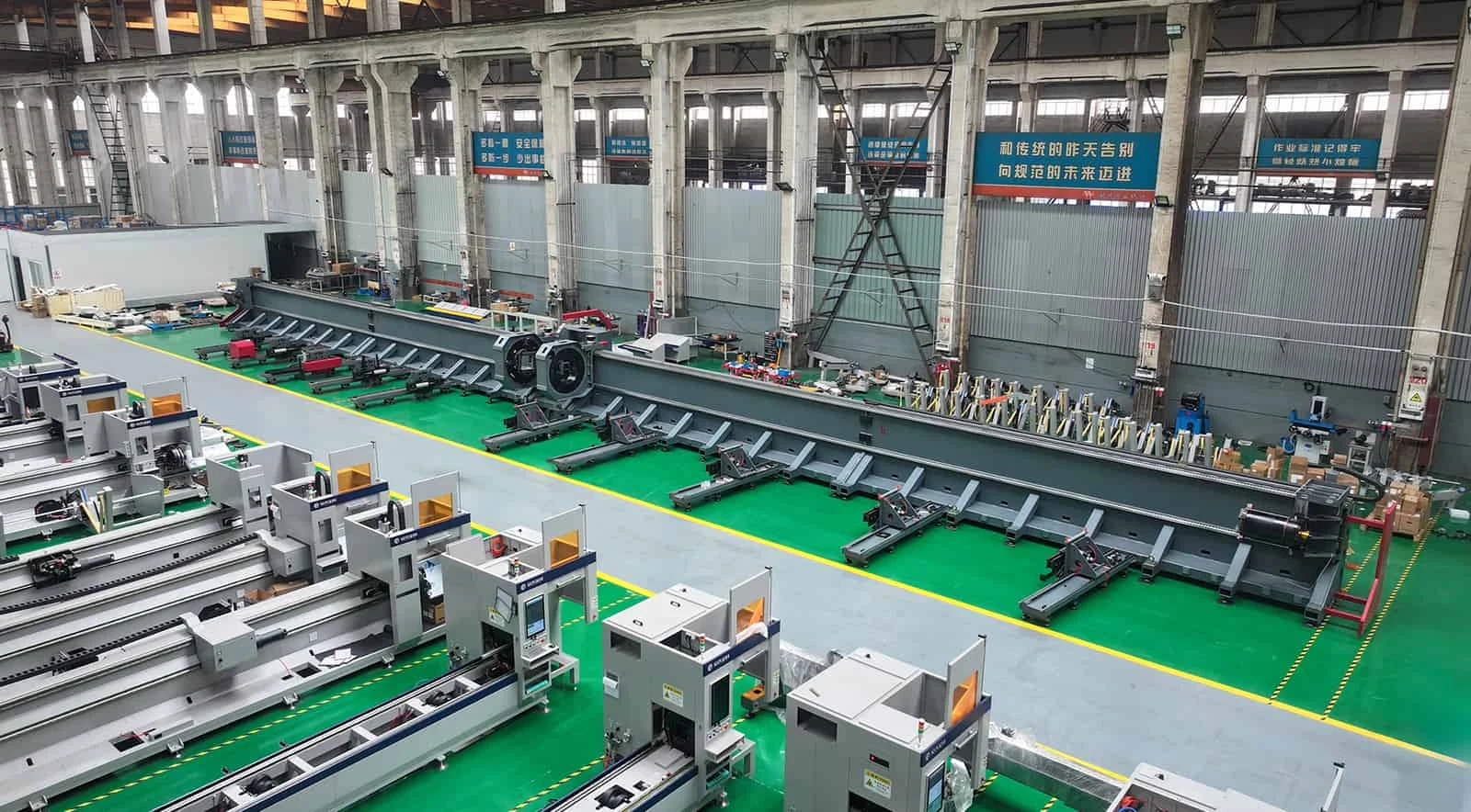
Anji Qingyun Intelligent Equipment Co., Ltd. operates a 50,000 m² factory and installs more than 100 machines per year. Overseas customers receive installation and commissioning guidance, training and spare-parts support.
Machine warranty: 1 year. Laser source: 2 years. Final terms follow the contract and configuration.
| Service | Available Support |
|---|---|
| English Documentation | English installation manuals, operation videos, and maintenance documents |
| Installation and Commissioning | Remote guidance for installation, commissioning, and parameter setup |
| Technical Support | Online troubleshooting and technical support, with a response within 24 hours |
| Training | Operator and maintenance training |
| Parts | Supply of wear parts, spare parts, and consumables |
| On-Site Service | When required and mutually agreed, an engineer can be arranged for on-site installation or repair |
| Local Support | Where available, support is provided by an overseas agent or local service partner |
| Warranty | 1 year for the machine and 2 years for the laser source; final terms follow the contract and configuration |
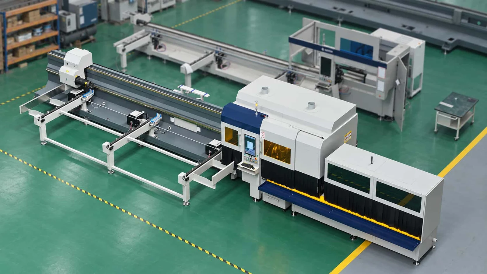
See an overseas installation
Supplied A22-C footage from Australia.
Before you choose.
What tube sizes and wall thicknesses can the A22-C cut?
It processes round tubes from Ø20 to 220 mm and square tubes from 20 × 20 to 220 × 220 mm. The minimum practical wall thickness is 0.6 mm. Maximum cutting thickness depends on the material, assist gas, and laser power; see the reference table above.
How short can the remnant be in zero-tailing mode?
In dual-chuck zero-tailing mode, the reference remnant is >5 mm for both straight and bevel cutting. Actual remnant length depends on the tube profile, clamping, nesting layout, and cutting method.
What is the difference between the A22-C and A22-CA?
With the A22-C, the operator places tubes on the staging rack and the machine feeds them to the chuck clamping position. The A22-CA is configured by project for fully automatic loading.
Which bevels can it cut?
It cuts bevels up to ±45°, including V- and Y-grooves for welding. The applicable range depends on the tube profile and chuck clamping conditions.
Can non-standard profiles use semi-automatic feeding?
Standard round, square, and rectangular tubes use the standard feeding process. Channels, angles, I-beams, oval tubes, and other non-standard profiles require manual assistance according to the actual shape.
Should I choose 3000W or 6000W?
Select the power level according to the material, maximum wall thickness, bevel requirements, and target output. Submit representative drawings to compare the corresponding configurations and test-cut results.
What information is needed for a quotation?
Provide the drawings, material, tube dimensions and wall thickness, stock length, and target output. Include any bevel requirements.
How are overseas installation and after-sales support provided?
We provide English documentation, remote installation and commissioning guidance, operator and maintenance training, and spare-parts support. Technical support requests receive a response within 24 hours; on-site service is arranged by project.
Start with your drawing.
Send the material, tube dimensions, wall thickness, stock length and target output. Include bevel requirements so we can recommend a configuration and arrange a sample test cut.
Send Your Tube Drawing