
How Accurate Is a Laser Cutter? Real Precision Tested
A laser cutter is accurate enough for your project when its finished parts meet the drawing’s tolerances under your actual production conditions. There is no single millimeter figure that applies to every machine, material and feature. Laser cutter precision depends on motion, material, workholding, the cutting process and measurement. The revealing question is whether the difficult features still fit after repeated cutting.
This page explains how to verify precision claims; it does not report a new machine benchmark.
Accuracy, Repeatability and Finished-Part Tolerance
Positioning accuracy, repeatability and part tolerance answer different questions. A specification becomes useful only after you identify which question its number answers.
| Term | What it describes | What it cannot establish alone |
|---|---|---|
| Positioning accuracy | How closely an axis reaches its commanded position | Finished hole or slot dimensions |
| Repeatability | How consistently an axis returns to a position | Freedom from systematic error |
| Finished-part tolerance | Acceptable limits for a specified feature | Consistency throughout a production batch |
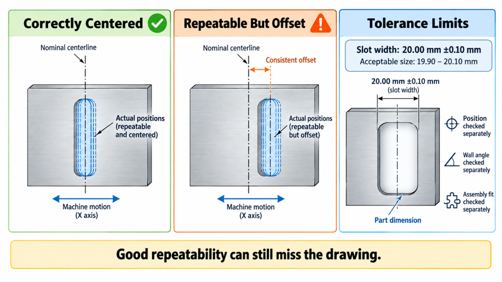
Good repeatability can coexist with an incorrect position. An axis may return consistently to the same offset location. That consistency does not establish that the finished feature matches the drawing.
A drawing tolerance applies to a particular requirement. For example, a hypothetical 20.00 mm slot with a ±0.10 mm size tolerance has acceptable limits of 19.90–20.10 mm. These figures illustrate tolerance arithmetic; they are not test results or a promised cutting capability. Slot position, wall angle and assembly fit require separate checks.
What Changes the Finished Dimensions?
Kerf compensation affects the final contour
Kerf is the width of material removed during cutting. The finished contour and the cutting path are therefore different geometries; CAD/CAM must account for that difference.
A single kerf-compensation value cannot cover every job. Material, thickness, assist gas and path direction affect the appropriate compensation. Changing those conditions calls for verification.
Small features expose limits that a large outside profile can hide. Narrow slots approaching the kerf width become harder to control and clear of scrap. The focused spot and kerf also limit sharp internal corners, which may require a radius or a relief feature.
Edge shape and heat can defeat a correct outline
A clean-looking top edge does not establish full cut quality. Taper, perpendicularity, roughness, burrs, dross and heat effects describe different characteristics. Inspect the ones that determine whether the part works.
Dense cutting paths can accumulate heat and deform the workpiece. Focus, power, speed, nozzle condition, gas and piercing strategy influence the result. Adjustments may involve path order, cooling time or process settings; increasing power alone cannot establish better accuracy.
Tube stock adds workholding and rotation errors
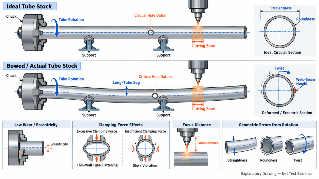
Tube cutting depends on the actual section as it moves and rotates. Straightness, roundness, twist and weld-seam height can shift the material surface away from the programmed model.
Clamping can alter the geometry being cut. Excessive force may flatten thin walls, while insufficient force may allow slipping or vibration. Chuck eccentricity, jaw wear, support-height errors and long-tube sag also affect feature position and focus distance.
Test Precision With Motion–Cut–Fit
Motion–Cut–Fit separates three kinds of evidence: axis performance, finished geometry and assembly function. It is a practical evaluation framework, not an accuracy standard.
1. Motion: identify what the specification measures
An axis specification needs its test conditions to support a comparison. Identify the measured axis, travel range, direction, measurement points and environment.
Comparable numbers must describe comparable tests. A rotary-axis repeatability figure cannot substitute for a finished slot-width tolerance. Keep linear motion, rotary motion and finished-part results separate.
2. Cut: test the features your work actually requires
A useful cutting trial starts with your intended material and drawing. Fix the material grade, thickness, equipment configuration, software and program versions, assist gas, measurement method and acceptance limits before comparing results.
Difficult features reveal more than an easy demonstration outline. Include the smallest relevant slot, critical hole positions and demanding contours. For tube applications, cover the thin-wall and long-stock conditions your jobs require.
Repeated cuts show whether the first successful part represents production. Compare results at startup, during stable running and after extended operation, using relevant stock positions. Agree on a sample quantity appropriate to the application; one passing sample proves only that sample’s result.
| Check | What to evaluate |
|---|---|
| Dimensions | Required lengths, hole diameters, hole positions and slot widths |
| Geometry | Specified contour position, end angle, taper or perpendicularity |
| Edge condition | Required limits for burrs, dross, roughness, oxidation and heat effects |
| Consistency | Results across relevant production times and stock positions |
| Measurement | Consistent datums, instruments, procedures and conditions |
A useful test report makes its limits visible. Record the drawing version, material, machine configuration, program version, measuring instrument, sample count and environment. The result applies to those conditions.
3. Fit: check the actual mating components
Passing individual dimensions does not establish assembly fit. Material thickness, section variation, coatings and welding shrinkage can change the available clearance.
Actual mating components provide the relevant functional check. For tube joints, assess contour fit, assembly gap and orientation against the drawing. Successful assembly supports that fit requirement; dimensional inspection still has its own role.
Could the Measurement Be Causing the Disagreement?
A measuring instrument must suit both the feature and its tolerance. Resolution, calibration and measurement uncertainty matter together. A fine digital display does not by itself establish a reliable result.
Thin walls can change shape under measuring force or different support conditions. Keep the datum, measurement points, direction, temperature and procedure consistent. Otherwise, two readings may reflect different inspection setups.
Inspection methods should follow the geometry. Hand tools, gauges, optical inspection, profile measurement and coordinate measurement suit different requirements. Select a method capable of evaluating the specified feature.
What Recognition and Automation Can Improve
Recognition and geometry measurement address errors beyond the programmed cutting path. Cross-section recognition, length measurement, weld-seam detection and geometric scanning can reduce the effects of loading direction and stock deviation. They cannot eliminate every material error.
Automatic parameter recall still depends on correct job information. Material, wall thickness, gas, nozzle and program must match the work. Incorrect inputs can produce repeated defects even when loading and cutting run automatically.
Machine comparisons should confirm these functions individually. Their existence in the industry does not establish their availability on a particular model, or prove a finished-part tolerance.
Laser Cutter Precision FAQs
How accurate is a laser cutter in millimeters?
No single millimeter value applies to every laser cutter and job. Use a finished-feature tolerance verified for the specified material, thickness, geometry and production conditions. An axis specification measures something different.
Is laser cutter precision the same as repeatability?
Repeatability describes consistency when returning to a position. Positioning accuracy describes closeness to the intended position. Finished-part results also depend on material, workholding, cutting conditions and inspection.
Does a smaller laser spot guarantee a more accurate part?
A smaller spot alone cannot guarantee the finished dimensions. Spot size affects small-feature capability, but kerf, motion, heat, workholding and measurement also influence the result.
Are fiber laser cutters more accurate than CO2 machines?
Laser type alone cannot establish a finished-part accuracy ranking. Compare suitable machines using the intended material, feature and acceptance requirement.
Does higher laser power improve accuracy?
Higher power does not automatically improve accuracy. Power interacts with focus, speed, gas and material; excessive heat input can deform thin sections or damage small features.
Why do laser-cut parts fail to fit when their dimensions look correct?
Fit also depends on edge geometry, burrs, material thickness, section variation and the mating component. Check the relevant geometry and assemble the actual parts.