
How It’s Made: The Laser Cutter Manufacturing Process
An industrial laser cutter is made by specifying the work it must perform, manufacturing its mechanical structure, integrating the laser source and motion systems, connecting utilities and controls, and validating the finished machine through movement tests and actual cutting. The laser cutter manufacturing process turns separate mechanical, optical, electrical, and software components into one coordinated system. The revealing part is how builders prove those components work together—not merely that the machine produces a beam.
This factory walkthrough focuses on industrial fiber laser cutters, with tube-cutting machines showing why workholding and material handling deserve as much attention as the laser itself.
Define the machine before building it
Start with the workpiece
The intended workpiece determines the machine’s architecture. Material, thickness, geometry, length, weight, feature size, and required output establish the design problem. A machine for long structural tubes faces different demands from one processing small, thin-walled tubing.
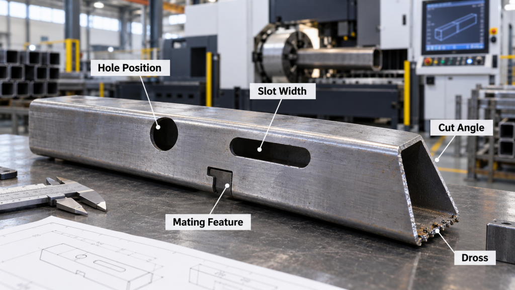
The specification must describe acceptable finished parts. Hole position, slot width, edge condition, bevel geometry, and assembly fit give engineers something measurable to build toward. “High precision” alone does not.
Separate component manufacturing from machine integration
A laser source, a cutting head, and a complete laser cutter are different products. The source generates the beam; the head directs and focuses it; the complete machine adds motion, workholding, utilities, software, and protection.
Specialist suppliers may provide major components. The machine builder still needs to define compatibility, integrate their functions, and establish responsibility for the finished system. Producing every component internally is a different question from delivering a capable machine.
Build the structure and motion system
Create the mechanical platform
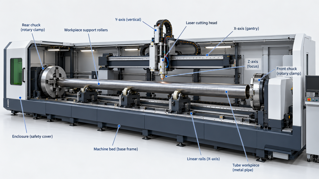
The mechanical structure establishes where the cutting head and workpiece can move relative to each other. The machine bed is one structural component; it does not establish the accuracy of the complete cutter by itself.
Structural manufacturing details require evidence from the specific factory. A finished enclosure cannot reveal the bed’s material, fabrication route, stress-relief process, or dimensional inspection history. A credible factory walkthrough connects the structural drawing to the manufactured component and its inspection record.
Add motion and workholding
Motion assembly creates the relationship between commanded movement and the physical cutting position. Linear and rotary movements need separate evaluation because they act on different parts of the machine.
Tube cutters add a moving workpiece to this relationship. Chucks grip and rotate the tube, while supports control sag and movement along its length. Their alignment and coordination affect where the beam meets the actual tube surface.
Clamping force can introduce its own errors. Excessive force can deform thin walls; insufficient force can allow slipping or vibration. Long tubes also need support conditions suited to their length, weight, and stiffness.
The practical manufacturing question is whether these assemblies work together across the intended material range. Checking a chuck or support in isolation cannot establish the performance of the complete handling system.
Integrate the laser and supporting systems
Connect the source, beam delivery, and cutting head
The optical system must match the intended cutting process. Output mode, beam quality, delivery fiber, focusing optics, and cooling requirements all influence the result. Two machines with the same nominal laser power can have different usable capabilities.
The cutting head performs several jobs at the interaction point. Its optical elements focus the beam, its nozzle delivers assist gas, and its sensing system helps maintain the working distance. Protective optics help shield sensitive components from contamination.
Optical cleanliness affects cutting stability. Contaminated protective windows can disturb performance, so inspecting them belongs in the same discussion as installing the source and head.
Treat utilities as part of the machine
Gas, cooling, extraction, and electrical systems support the cutting process. Gas type and delivery affect molten-material removal and edge condition; cooling supports the laser system; extraction removes process fumes.
Laser output power is different from total machine electrical power. Neither figure alone establishes production capacity, and a power label cannot replace a complete configuration description.
| Integrated system | What to verify |
|---|---|
| Laser source and head | Compatible operating requirements and intended process |
| Motion and workholding | Coordinated travel, rotation, clamping, and support |
| Gas and cooling | Requirements matched to the installed configuration |
| Extraction and protection | Process hazards addressed across operating modes |
| Controls and software | Correct commands, interfaces, and machine responses |
Make software coordinate physical movement
Turn geometry into a machine sequence
CAD/CAM and CNC controls connect the drawing to physical action. Software generates paths, applies process settings, and coordinates movement with cutting commands.
A tube program must account for handling as well as geometry. Feeding, rotation, chuck positions, support movement, head motion, and clearance constraints all affect whether the programmed part can become a real one.
A successful software demonstration should use representative parts. A prepared demonstration file may show the interface clearly without testing the difficult features or handling conditions the machine must eventually manage.
Extend integration beyond the cutting zone
Current system development reaches into loading, changeover, measurement, unloading, sorting, and production data. These functions expand what manufacturers must integrate and validate.
Automatic loading does not establish automatic production. Material separation, orientation, finished-part handling, scrap capacity, and exception recovery can still interrupt the sequence.
Material-handling compatibility follows the overlap between connected systems. A loader’s capacity cannot expand the cutting machine’s permitted tube size, weight, or process range.
Data interfaces also need physical meaning. An order number, material batch, program version, and destination should remain connected to the correct part as it moves through the cell.
Prove the machine through three validation gates
A useful way to understand commissioning is to divide it into three gates: motion, process, and production. This framework separates questions that a single demonstration cut cannot answer.
Gate 1: Does the machine move correctly?
Axis testing evaluates machine movement. Positioning accuracy describes deviation from a commanded position; repeatability describes consistency when returning to that position under defined conditions.
Good repeatability does not guarantee correct absolute position. A machine can repeatedly return to the same wrong location.
Tube machines need further distinctions. Linear-axis performance, rotary-axis performance, chuck concentricity, and head-following behavior describe different relationships. Combining them into one unexplained “accuracy” figure hides useful information.
Gate 2: Does the process make an acceptable part?
Cutting trials evaluate the interaction between machine, material, and settings. Focus, nozzle alignment, gas, speed, power, and piercing strategy all influence kerf width, edge condition, heat effects, and dimensional results.
Finished-part inspection must follow the drawing. Length, holes, slots, angular relationships, bevels, and assembly features may require different measurement methods.
A good-looking edge cannot prove correct geometry. A part may look clean yet have misplaced holes or an unacceptable fit.
Gate 3: Can the machine sustain acceptable production?
Production validation examines repeated output under agreed conditions. The first acceptable sample does not establish performance after warm-up, repeated loading, material changes, or extended operation.
Elapsed production time must include the whole sequence. Loading, measurement, adjustment, piercing, cutting, travel, unloading, sorting, and interruptions all contribute to output.
Measurement records make that output assessable. Useful records identify the drawing, material, machine configuration, program, instruments, sample count, and test conditions.
Follow the error instead of guessing
An uneven tube cut should prompt investigation across connected systems. Beam-to-nozzle alignment, material geometry, clamping, support, focus, gas, and motion can all matter.
An illustrative troubleshooting question is: why does one side cut cleanly while another retains dross? The knowledge base identifies beam-to-nozzle alignment as one relevant check. That observation guides investigation; it does not prove every similar symptom has the same cause.
The broader lesson is to verify a suspected cause before changing production settings. A small trial and inspection can establish whether the adjustment helped.
Follow the machine through delivery
Preserve the acceptance evidence
Factory acceptance should connect the delivered configuration to its test results. Samples become more useful when their drawings, programs, settings, timing records, and measurements remain identifiable.
Safety verification belongs to the complete machine. Laser radiation, moving mechanisms, rotating workpieces, electrical equipment, pressure gases, fumes, and maintenance access create different hazards.
Operating modes need distinct consideration. Production, setup, manual intervention, and maintenance place people in different relationships with the equipment.
Confirm performance at the installation site
Site acceptance establishes what the installed machine can do under its actual conditions. Foundations, space, lifting access, electricity, gas, cooling, extraction, and material flow all affect deployment.
The manufacturing process reaches a meaningful endpoint when the installed system produces acceptable parts under defined conditions. The strongest factory story follows that evidence from individual components to repeated output.
Frequently asked questions
How is a laser cutter manufactured?
Manufacturers define its intended work, produce the mechanical structure, integrate optical and motion systems, connect controls and utilities, and test the finished machine.
Does the machine manufacturer also make the laser source?
It may manufacture the source or obtain it from a specialist supplier. Source manufacturing and complete-machine integration are separate responsibilities.
What is the difference between manufacturing a laser cutter and laser cutting?
Manufacturing a laser cutter creates the equipment. Laser cutting uses that equipment to separate or shape material with a focused beam and assist gas.
Why do tube laser cutters need chucks and supports?
Chucks hold and rotate the tube, while supports control sag and movement. Both influence the relationship between the programmed path and the actual surface.
Does higher laser power make a better cutter?
Higher power can expand some processing capabilities, but usable performance also depends on optics, motion, gas, workholding, material, and required quality.
How do manufacturers check laser cutter accuracy?
They distinguish axis tests from cutting trials and finished-part inspection. Each test needs a defined object, method, range, and set of conditions.