
How Does a Laser Cutter Work? Key Process & Mechanism
A laser cutter works by focusing a laser beam onto a small area, heating the material until it melts, burns, or vaporizes, then moving along a programmed path to separate the part. In industrial metal cutting, assist gas removes molten material from the narrow opening, called the kerf. The laser cutting process succeeds when energy, material removal, and motion work together—and that explains why more laser power alone cannot guarantee a better cut.
This guide focuses on industrial metal cutting, with tube-cutting examples where the mechanics differ from flat-sheet processing.
The Laser Cutting Mechanism: Heat, Clear, Move
Think of laser cutting as three linked jobs: heat the material, clear the kerf, and move the cut. This “Heat–Clear–Move” model helps beginners connect machine components to the result they can see.
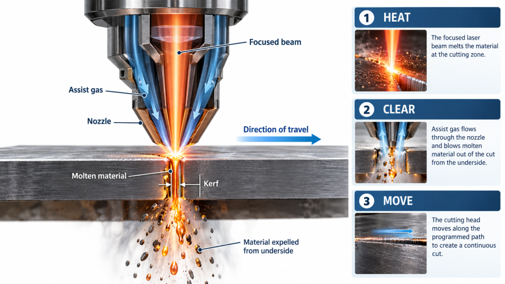
Heat: Concentrate Energy
The cutting head concentrates the beam’s energy into a small working area. The laser source generates the beam; the delivery system carries it to the head, where optics focus it onto or within the material.
Industrial metal cutting often uses a near-infrared fiber laser. Its source generates and amplifies laser light in an optical fiber. Other laser types have different wavelengths, outputs, and material compatibility, so the word “laser” alone does not identify what a machine can cut.
Focus determines where the beam concentrates its energy. Rated power describes energy output per unit time, but cutting also depends on spot size, material absorption, focus position, and travel speed.
Clear: Remove Material
Heating creates the conditions for a cut, but material must leave the kerf to separate the workpiece. In metal cutting, gas flows through the nozzle and helps eject molten material.
The assist gas can change both the mechanism and the finished edge. Oxygen adds heat through an oxidation reaction. Nitrogen or argon mainly helps expel molten material and limits oxidation under suitable process conditions.
| Assist gas | Main contribution | What to check |
|---|---|---|
| Oxygen | Supports oxidation and adds heat | Whether the resulting oxide layer suits later operations |
| Nitrogen | Expels molten material while limiting oxidation | Purity, supply conditions, edge quality, and gas consumption |
| Argon | Provides inert shielding and melt removal | Application suitability and operating cost |
Much industrial metal laser cutting relies on melting and ejection rather than vaporizing the entire kerf. Describing every cut as “the laser vaporizes the material” hides the role of gas and makes common defects harder to understand.
Move: Follow the Contour
The CNC system coordinates motion with the cutting conditions. It converts the programmed geometry into axis movements and coordinates the laser, gas, and other machine functions.
Cut quality depends on controlled relative motion between the beam and workpiece. Straight sections, corners, small holes, and dense features place different demands on motion and heat control. A machine’s maximum travel speed therefore does not equal its usable cutting speed.
The Laser Cutting Process, Step by Step
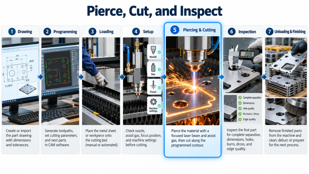
A complete laser cutting process begins with the drawing and ends with an inspected part. Beam-on time covers only part of that work.
Prepare and Set Up
- Define the part and acceptance requirements. Confirm material, thickness, geometry, dimensions, edge condition, and any later welding or coating requirements.
- Prepare the CAD/CAM program. Generate paths, arrange parts, apply suitable kerf compensation, and check available collision controls. Software capabilities depend on the configuration.
- Load and support the material. Position the sheet or clamp the tube securely. Tube jobs also require attention to straightness, rotation, support, and seam orientation where relevant.
- Select a validated process setup. Match power, speed, focus, nozzle, gas, and piercing strategy to the material and thickness. Check cooling, extraction, and protective systems before operation.
Pierce, Cut, and Inspect
- Establish the opening and follow the path. Piercing creates a starting opening where the geometry requires one. The machine then coordinates heating, gas flow, and movement along the contour.
- Inspect the first part before continuing production. Check complete separation, dimensions, holes, burrs, dross, and edge condition. Confirm settings with a small trial after adjustments.
- Unload and complete any finishing work. Some parts still need cleaning, deburring, or other processing. Automatic cutting does not prove that a part is ready for assembly.
Why the Same Laser Can Produce Different Results
Cut quality comes from a process window, not one specification. Material grade, thickness, surface condition, optics, gas, nozzle condition, and motion all influence the result.
The three-part model provides a useful first diagnostic framework. A defect may involve more than one category, so use it to organize checks rather than declare a cause from appearance alone.
| Visible problem | Possible contributors | Investigation priority |
|---|---|---|
| Incomplete separation or heavy bottom dross | Power, speed, focus, gas, nozzle, or piercing | Check the complete process setup |
| Good cutting on one side, poor cutting on another | Beam–nozzle alignment or related conditions | Have trained personnel check alignment and head condition |
| Irregular tube features | Clamping, support, material geometry, or motion | Check the workpiece as well as the laser settings |
| Quality deteriorates during a run | Optical contamination or changing process conditions | Inspect equipment condition and compare later parts with the first |
Increasing power is an unreliable universal fix. Thin-wall tube damage can involve excessive heat input, while thick-wall cutting problems may involve focus, gas, nozzle size, or piercing as well as power.
A neat edge does not prove dimensional accuracy. Kerf width, taper, thermal effects, and workpiece movement can affect fit even when a cut looks clean. Inspect the features that determine whether the part will assemble correctly.
What Changes When Cutting Tubes?
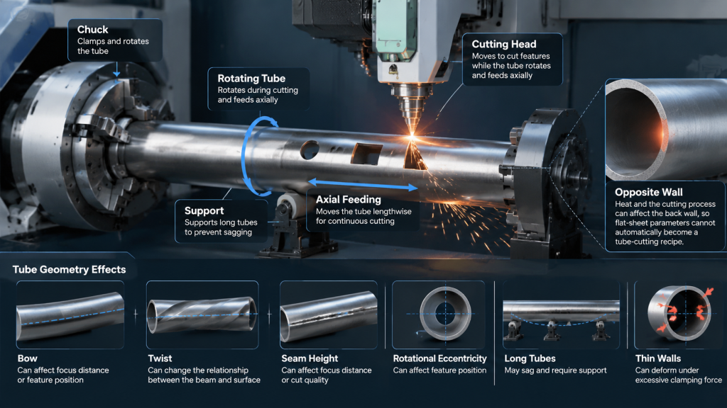
Tube cutting adds rotation and workpiece control to the basic mechanism. The machine coordinates axial feeding, tube rotation, cutting-head movement, clamping, and support.
Tube geometry can change the relationship between the beam and the surface. Bow, twist, seam height, and rotational eccentricity can affect focus distance or feature position. Long tubes may sag, while thin walls can deform under excessive clamping force.
The opposite wall creates another constraint. Heat and the cutting process can affect the back wall, so a flat-sheet parameter set cannot automatically become a tube-cutting recipe.
Non-contact cutting still requires stable workholding. The beam does not push against the material like a saw, but the machine must hold and move the workpiece consistently.
What New Buyers Should Verify
Ask suppliers to demonstrate your parts under agreed conditions. Use representative material, difficult features, relevant lengths, and consecutive parts rather than judging capability from one attractive sample.
Compare completed production cycles. Include loading, measurement, adjustment, piercing, cutting, unloading, sorting, and finishing. A faster cut may deliver little benefit if another stage limits output.
Ask what each automatic function actually does. Technology development increasingly involves measurement, seam or contour recognition, automatic adjustment, and integrated handling. Availability and performance remain configuration-dependent.
Define accuracy at the finished-part level. Axis positioning accuracy and repeatability describe machine behavior; they do not guarantee the dimensions of every cut component.
Evaluate the complete working system. Cooling, extraction, gas supply, guarding, interlocks, maintenance, and training all contribute to reliable operation. “Fully automatic” alone does not establish unattended capability.
Frequently Asked Questions
Does a laser cutter melt or vaporize metal?
Industrial metal laser cutting commonly melts material and uses assist gas to remove it. Oxygen-assisted cutting also uses oxidation heat. The dominant mechanism depends on the application.
What does assist gas do in laser cutting?
Assist gas helps clear material from the kerf and influences edge chemistry. Its type, purity, pressure, flow, and nozzle delivery can affect dross, oxidation, and subsequent processing.
Is laser cutting the same as CNC cutting?
Laser cutting describes the cutting method; CNC describes the control method. A CNC machine can use other tools or processes, so CNC alone does not mean laser cutting.
Does higher laser power always mean faster cutting?
Higher power alone does not establish usable cutting speed. Material, thickness, beam characteristics, gas, motion, and the required quality also constrain performance.
Can one laser cutter cut every material?
Material compatibility depends on the complete system and process. Wavelength, absorption, reflectivity, heat conduction, coatings, and machine configuration all matter.
Why does laser cutting leave burrs or dross?
Burrs and dross can indicate problems with melt removal or the wider process setup. Check material, focus, speed, power, gas, nozzle, and alignment before committing to production.