
How Do Fiber Laser Cutting Machines Work? From Beam Focusing To Slit Formation
Fiber laser cutting machines use a focused beam of light to melt metal, and then use auxiliary gas emitted from a nozzle to discharge the molten material from under the sheet. The cutting head moves along the CNC program, melting the metal in front and leaving a slit at the back that runs through the thickness of the plate. Taking a common ytterbium-doped fiber laser as an example, the light beam gains gain in the ytterbium-doped fiber inside the laser and is then sent to the cutting head through the transmission fiber. What the whole machine needs to do is to ensure that the beam, airflow, and motion are always in sync. LUT University Steel Fiber Laser Cutting Research · Ytterbium-doped Fiber Laser Research
The laser is generated in the light source and focused in the cutting head
The semiconductor laser diode emits pump light first. The ytterbium-doped optical fiber inside the light source absorbs the pump light, and the ytterbium ions in the fiber core are excited, transferring energy to the laser through stimulated radiation. The transmission fiber at the output receives the beam and sends it to the movable cutting head. The two sections of optical fiber have a clear division of labor: one section provides optical gain, and the other section is responsible for delivery. Ytterbium-doped fiber laser research · Fiber laser perforation test device
After the light beam leaves the transmission fiber, the collimator in the cutting head first turns the diverging light beam into an approximately parallel light beam, and then the focusing mirror bundles it into a small spot. The same laser power is concentrated on a smaller area, resulting in a higher power density. The position of the focus relative to the plate surface will also change the size of the light beam in the plate thickness direction, thereby affecting the width of the upper and lower openings of the cut. This geometric change will affect the next step of slag removal. Fraunhofer IWS Stainless Steel Fiber Laser Cutting Test
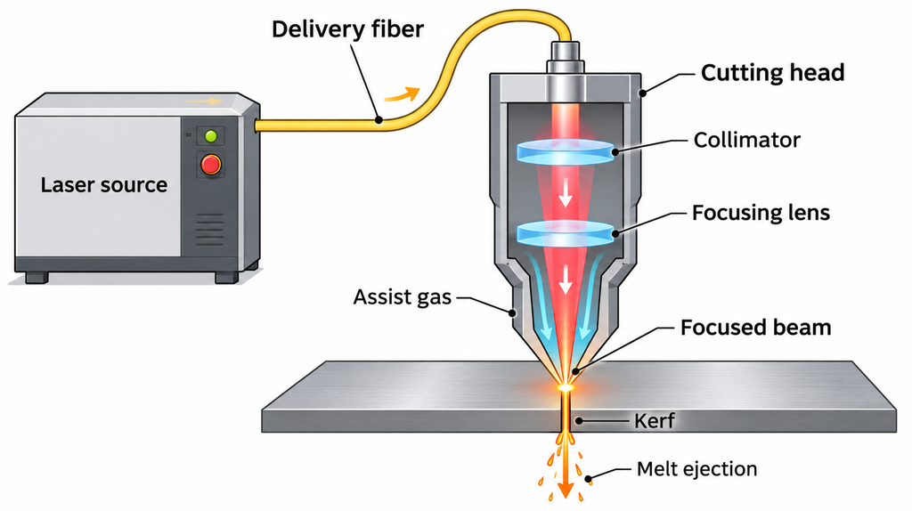
Auxiliary gas discharges the melt and oxygen also provides heat
During cutting, the light beam illuminates the cutting edge, and the metal absorbs energy to form a molten film. The auxiliary gas enters the cutting seam along the beam axis through the nozzle, pushing the molten material downward along the cutting front and discharging it from the bottom of the plate. When discharge is insufficient, some of the molten material will solidify at the lower edge, forming slag. Fraunhofer IWS Melt Cutting Research
When cutting stainless steel with nitrogen, the heat required for melting comes from the laser. The nitrogen is responsible for expelling the molten metal and inhibiting oxidation of the cut edges. When oxygen is used to help cut low-carbon steel, the oxygen is also responsible for discharging the molten material and will also react exothermically with the heated iron to replenish heat for cutting. Cutting the edges will leave an oxide layer. If the part is to be welded or painted next, whether this layer of oxide needs to be removed depends on the requirements of the subsequent process for cutting edges. LUT University Nitrogen Melt Cutting and Oxygen Co-cutting Test
When cutting from inside the plate, the machine perforates first and then moves the knife along the contour
Taking cutting a sheet metal part with a circular hole as an example, the cutting head first passes through the hole in the area to be removed inside the circular hole. The orifice left by the perforation may be wider than the normal cutting seam, so the procedure usually arranges a short lead-in line to allow the cutting head to enter the circular outline from the perforation point, leaving the cut mark on the waste side. As the cutting tool moves along the contour, the CNC system controls the planar movement of the cutting head, and the laser and airflow continuously act on the cutting front. University of Nottingham Fiber Laser Cutting Research · Laser Perforation Process Experiment
The cutting head also needs to follow the height of the board surface. Models that use capacitance-dependent operation estimate the gap by using the capacitance change between the nozzle and the metal plate, and then maintain the set distance by raising and lowering the Z axis. There are two locations to see clearly. The nozzle gap is measured by the distance from the nozzle outlet to the plate surface, and the focus position is measured by the position of the thinnest part of the beam relative to the plate surface. The former affects how the airflow enters the cut, and the latter affects the distribution of laser energy in the thickness direction of the plate. Cutting Head Capacitance Ranging Prototype Study, Page 118 · Fraunhofer IWS Focus Position and Nozzle Gap Test
Why is it cut through, or is it possible to cut rough?
Cutting through only means that the cut seam runs through the thickness of the board. How rough the cut surface is and whether there is slag hanging on the bottom of the plate also depend on how the molten material flows in the seam and whether it can be discharged in time. The faster the knife moves, the shorter the time the beam of light acts in the same position. The change in focus simultaneously alters the heating position and the shape of the slit, which in turn changes the conditions under which the airflow discharges the melt. Fraunhofer IWS Cut Geometry and Cut Edge Roughness Test
Fraunhofer IWS uses nitrogen and fiber laser cutting to cut 10 mm thick AISI 304 stainless steel. The researchers selected various parameters that could cut through the plate, but the cross-sectional performance was different. Some samples had a large amount of molten material accumulated on the upper part, while others had insufficient slag discharge on the lower part of the cross-sectional surface. Under the test conditions of this set of fixed beams, the focal position is the main factor affecting the shape of the cut. When looking at the test cut, you can look at three parts separately: whether the outline is completely cut, whether the grain on the cut surface suddenly thickens in the direction of the plate thickness, and whether there is slag hanging on the lower edge. They reflect the cut-through, cut-surface state, and slag removal results, respectively. Fraunhofer IWS test Figures 4, 9, and 11